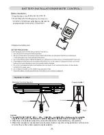
BATTERY INSTALLATION(REMOTE CONTROL)
directions
.)
-9-
Remote Control
ment as the figure on right and the
polarity markin
battery door and lift it off.
2.Install two(2)x A A A size
.
.
Remarks:
2. When there is an obstacle between the unit and the transmitter, the transmitter may not operation.
3. When direct sunlight, an incandescent lamp, fluorescent lamp or any other strong light shines on the remote
control of the unit, the remote operation may be unstable.
Fig.2
Fig.1
Power Amplifier:
,.
,.
,.
V-
V+
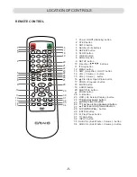
1. The AMP ON/OFF INPUT VOL + VOL - SUB VOL - and SUB VOL + Buttons are for Amplifier
only. When using face the Remote Control to Amplifier s Remote Sensor as figure 2 above.
,.
,
,

