background image


19

Connect the cord to the power source and 
turn the table saw “ON”. Let the blade reach 
the full speed and feed the work-piece 
through the blade using a push stick, until 
the work-piece completely passes the saw 
blade. See figure-29. 


Figure-29 Ripping operation 


After the work-piece is cut, let the blade 
come to a complete stop and then remove 
the cut-off pieces. 


CROSSCUTTING 


Cutting solid wood across the grain and 
cutting plywood across the width of the 
work-piece is called cross-cutting. 
 
Remove the fence and mark the work-piece 
where you want to start the cut. Set the 
miter gauge to the correct angle. Place the 
work-piece on the table so that the marked 

point is aligned with the blade and the blade 
is cutting the waste side of the line.  
 
Connect the cord to the power source and 
turn the table saw “ON”. Let the blade reach 
its full speed and hold the work-piece 
against the face of the miter gauge. Slowly 
push the work-piece with the miter gauge 
and until it is completely past the blade. Let 
the blade come to a complete stop and 
remove the cut-off work-pieces. 


Figure-30 Crosscutting operation 


MITER CUTS 


Miter cut is an angled crosscut performed in 
the same manner as a crosscut, using the 
miter gauge. 
 
Place the face of the miter gauge against 
the edge of the work-piece and miter gauge 
bar across the face of the work-piece. Use 
the bar as a guide and mark the angle of 
cut with a pencil as shown in figure-31. 
 
Place the miter gauge back into the T-slot 
and hold the work-piece against the face of 
the miter gauge. Push the work-piece with 
the miter gauge slowly against the blade 
until the work-piece is completely past the 
blade.  


WARNING! 

Do not use your fingers to feed narrow 
work-pieces into the blade. Always use a 
push stick to prevent the possibility of 
injury. 

Summary of Contents for CX204N

Page 1: ...MODEL CX204N 10 SCORING TABLE SAW WITH RIVING KNIFE 30 RIP FENCE User Manual VER 1 1 ...

Page 2: ... 12 Table Insert 13 Installing the Blade Guard 13 Basic Controls 14 Test Run 14 Connecting to a Dust Collector 15 Blade Guard 15 Riving Knife 16 Scoring Saw Blade 16 Adjusting the Scoring Blade 16 Work Piece Inspection 17 Operations 18 Through Cuts 18 Non Through Cuts 18 Ripping 18 Crosscutting 19 Miter Cuts 19 Bevel Cuts 20 Main Table to Blade Parallelism 20 Spreader Riving Knife Alignment 21 Rep...

Page 3: ...chine BE ALERT DO NOT use prescription or other drugs that may affect your ability or judgment to safely use your machine DISCONNECT the power source when changing drill bits hollow chisels router bits shaper heads blades knives or making other adjustments or repairs NEVER leave a tool unattended while it is in operation NEVER reach over the table when the tool is in operation ALWAYS keep blades k...

Page 4: ... to a complete stop and the power switch has been turned to the OFF position and cord is unplugged NEVER attempt to cut stock freehand always use the rip fence or miter gauge ALWAYS make sure that the rip fence is properly squared to the saw blade to prevent kickback ALWAYS make sure that your saw is in a stable position Cutting heavy long stock may alter the stability of the saw In the event that...

Page 5: ... safety procedures should be adhered to Motor 3 HP 220 V Single Phase TEFC Motor Miter Gauge T Slot Miter Gauge Table Size Length 27 x Width 44 5 with Extension Wings Floor to Table Height 36 Maximum Blade Diameter 10 Riving Knife Spreader Thickness 0 1 Blade Tilt Right Arbor Size 5 8 Blade Speed 5200 RPM Scoring Blade Diameter 3 Scoring Blade Bore 0 78 Scoring Blade Teeth 20 Fence Size 30 Maximum...

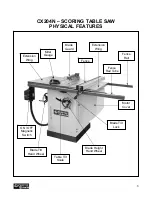
Page 6: ... SAW PHYSICAL FEATURES Blade Guard Motor Cover Miter Gauge Blade Tilt Hand Wheel ON OFF Magnetic Switch Blade Height Hand Wheel Blade Tilt Lock Extension Wing Table Tilt Scale Extension Wing Fence Fence Rail Fence Rail Tube ...

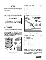
Page 7: ... machine and the parts are in good condition Figure 1 Inventory LIST OF CONTENTS QTY A Table Saw 1 B Extension Wings 2 C 10 Blade 1 D Table Insert 1 E Riving Knife 1 F Spreader 1 G Motor Cover 1 H Push Stick 1 Figure 2 Inventory LIST OF CONTENTS QTY I Hand Wheels 2 J Hand Wheel Locks 2 K Hand Wheel Handles 2 L Blade Guard 1 M Miter Gauge 1 N Scoring Blade 1 O Fence 1 P Fence Rail and Tube 2 Q Hard...

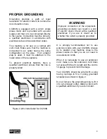
Page 8: ...an ensure that the line is properly wired Figure 3 220 Volts Outlet for CX204N It is strongly recommended not to use extension cords with your CX204N Always try to position your machine close to the power source so that you do not need to use extension cords When it is necessary to use an extension cord make sure the extension cord does not exceed 50 feet in length and the cord is 12 gauge to prev...

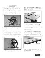
Page 9: ...it using the lock Thread the handle into the hole on the hand wheel and tighten it properly See figure 5 Figure 5 Installing blade tilt hand wheel Attach the extension wings to the two sides of the table using nuts bolts and washers provided See figure 6 Figure 6 Installing the extension wings Place a straight edge on the main table and the extension wing and make sure they are flat with each othe...

Page 10: ... the hinges and locking using the screw provided as shown in figure 9 Figure 9 Installing the motor cover Attach the front fence rail to the table and extension wings using bolts nuts and washers provided See figure 10 Figure 10 Installing front fence rail Now install the fence rail tube onto the front rail using cap screws washers and flat washers provided See figure 11 Figure 11 Installing the f...

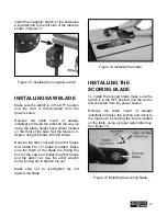
Page 11: ...bor nut and the arbor flange and install the 10 blade provided Make sure the teeth of the blade are facing the front of the saw and install the arbor flange and the arbor nut Use the arbor wrench and a locking pin to tighten the nut Make sure not to over tighten the nut against the blade Figure 14 Installing the blade INSTALLING THE SCORING BLADE To install the scoring blade make sure the switch i...

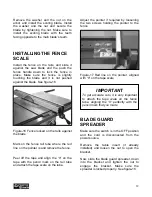
Page 12: ...ter is and remove the fence Peel off the tape and align the 0 on the tape with the pencil mark on the rail tube and attach the tape scale on the tube Adjust the pointer if required by loosening the two screws holding the pointer to the fence Figure 17 Red line on the pointer aligned with 0 on the tape scale BLADE GUARD SPREADER Make sure the switch is in the OFF position and the cord is disconnect...

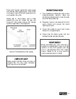
Page 13: ...ke sure it is level with the table surface secure it by tightening the two screws See figure 19 Figure 19 Installing the table insert INSTALLING THE BLADE GUARD Attach the blade guard to the spreader as shown in figure 20 Figure 20 Installing the blade guard Once the blade guard is attached to the spreader slide the blade guard back wards and push the lock handle down to lock the blade guard on th...

Page 14: ...eight TEST RUN Once you have assembled your machine completely it is then time for a test run to make sure that the machine works properly and is ready for operation During the test run if there is any unusual noise coming from the machine or the machine vibrates excessively stop the machine immediately and disconnect from the power source and investigate to find out the problem with your machine ...

Page 15: ... fed into the blade and returns to the table surface when the work piece has passed through the blade It prevents the wood chips to fly and injure the operator and it also prevents from accidental contacts of objects with the blade At the back side of the guard there is a metal plate called a spreader The spreader prevents the kerf of the work piece from pinching the blade and causing kick back Th...

Page 16: ... between the blade from the carbide tip and the riving knife Figure 25 Riving knife SCORING SAW BLADE The CX204N can run two blades at the same time One is a regular circular saw blade and the other is a small blade that is installed in front of the main one The smaller blade rotates in the opposite direction to the main blade cutting from the underside of the panel where the damage usually happen...

Page 17: ... stable while cutting This situation can be dangerous because during operation the work piece can move un expectedly which can either damage the blade or hurt the operator If the wood is slightly cupped make sure the cupped face of the wood is held against the table or the fence If the bowed side of the work piece is held against the table or the fence there will be a great possibility that the wo...

Page 18: ...it does not cut the work piece all the way through its thickness is called non through cut Since the blade guard can not be used when doing non through cuts there is great possibility of kickback Make sure to have the riving knife installed when using standard saw blade to perform non through cuts Figure 28 Shows an example of non through cut with standard saw blade For clarity figure 28 does not ...

Page 19: ...urn the table saw ON Let the blade reach its full speed and hold the work piece against the face of the miter gauge Slowly push the work piece with the miter gauge and until it is completely past the blade Let the blade come to a complete stop and remove the cut off work pieces Figure 30 Crosscutting operation MITER CUTS Miter cut is an angled crosscut performed in the same manner as a crosscut us...

Page 20: ...quality To check if the table is parallel to the blade use an adjustable square and measure the distance between the miter slot on the table and the edge of the blade front or back as shown in figure 32 Figure 32 Measuring the distance using an adjustable square Now lock the square in place and mark the blade with a marker where you made the measurement Rotate the blade so that the mark is opposit...

Page 21: ...nd increasing the risk of kick back Make sure the switch is OFF and check the spreader or riving knife alignment using a straight edge Raise the blade to the maximum height using the blade height hand wheel Place the straight edge against the top and bottom part of the spreader or riving knife as shown in figure 34 Figure 34 Using a straight edge to check the top and bottom alignment If the spread...

Page 22: ...g bolt as shown in figure 36 and push the motor up to loosen the tension on the main belt Figure 36 Loosening the motor mounting bolt Remove the main belt from the pulleys and install the new one Move the motor down to tension the main belt and retighten the bolt Replace the small belt with a new one and install it onto the rollers and pulleys and close the motor cover MITER GAUGE ADJUSTMENT The m...

Page 23: ...hould be protected with a coat of paste wax and then buffed dry 2 Regularly vacuum all sawdust from the saw s interior and vacuum the motor openings as well 3 Check drive belts for wear and correct tension on a regular basis 4 Check that the blade guard and anti kickback pawls operate properly IMPORTANT Miter gauge provides close accuracy in angled cuts For very close tolerance test cuts are recom...

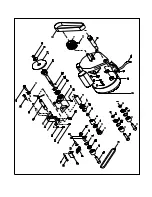
Page 24: ...24 CX204N PARTS BREAKDOWN ...

Page 25: ...25 ...

Page 26: ......

Page 27: ......

Page 28: ......

Page 29: ...UNNION 1 15 12900009 REAR TRUNNION 1 16 13100006 TRUNNION BRACKET 2 17 13100007 DUST COVER 1 18 W1230002 SWITCH 1 19 12500008 ROD CAP 1 20 C1106201 BEARING 6201 1 21 129A0022 ANGLE ROD 1 22 12900013 HAND WHEEL SPINGLE 1 23 20900023 GEAR AXLE SLEEVE 2 24 20900024 RING 2 25 20900022 BEVEL GEAR 2 26 20900028 SLEEVE 2 27 12900031 ELEVATION ROD 1 28 12900014 GEAR COVER 1 29 20900019 ROD SLEEVE 1 30 129...

Page 30: ... BLADE SLEEVE 1 51 12300134 PULLEY 1 52 12300132 CONNECTOR FIXER 1 53 12300133 ADJUSTING ROD 1 54 12300128 SCORING BLADE CONNECTOR SPINDLE 1 55 12300130 SPRING 1 56 12300131 BUSHING 1 57 12300137 PULLEY BRACKET 1 58 C1106000 BEARING 3 59 12300135 PULLEY 3 60 12300103 PULLEY SPACER 2 61 12900033 SPRING 1 62 12900036 SPRING FIXED PLATE 1 63 V1310002 BELT 1 64 12300168J MAGNET 1 65 S0021016M HEX SCRE...

Page 31: ...1 90 12900039 QUICK RELEASE SCREW 1 91 S0050810M SET SCREW M8 P1 25 10L 4 92 12900040 QUICK RELEASE NUT 1 93 S1020580 LOCK NUT 5 8 11UNC 1 94 S0210540 FLAT WASHER 5 8 16 21 1 95 S0011055M CAP SCREW M10 P15 55L 3 96 S0121000M LOCK NUT M10 P15 1 97 S0110800L HEX NUT M8 1 25L 1 98 S0230800M SPRING WASHER Ø8 13 99 S0210516 FLAT WASHER Ø8 16 2t 11 100 S0050606M SET SCREW M6 P1 0 6L 4 101 S0050303a SET ...

Page 32: ...1105080 SPRING 1 132 11102020M HEX SCREW M6 P1 0 1 133 S0020812M HEX SCREW M8 P1 25 12 2 134 S0030520M ROUND HEAD SCREW M5 P0 8 20 2 137 L0000000 WIRE 1 138 L0000000 MOTOR CORD 1 139 C9001920 BEARING 4 140 12900038 QUICK RELEASE HANDLE 1 141 S009AN04 BEARING NUT AN04 M20 P1 0 1 142 12900037 SHAFT BUSH 1 144 11305031 LOCKING NUT 2 145 S0920017 OPEN END WRENCH 17mm 1 146 S0920019 OPEN END WRENCH 19m...

Page 33: ...0304 PHILLIPS HEAD SCREW M5 P0 8 8L 2 A11 S0120600M LOCK NUT M6 P1 0 10 A12 S0210404 FLAT WASHER 1 4 23 3t 8 A13 S0310630 PIN Ø6 30 1 A14 S0313528 PIN Ø3 5 28 1 A15 S0310530 PIN Ø5 30 2 A16 S05ETW07 E RING ETW 7 2 A17 12700051a SLEEVE 1 A18 12700039a PAD 1 A19 S0010512M CAP SCREW M5 P0 8 12L 2 A20 S0020635M CAP SCREW M6 P1 0 35 1 A21 12700054 HANDLE 1 A22 S0040620M CROSS HEAD SCREW M6 P1 0 20L 4 A...

Page 34: ... 1 B3 B4 B3 10104045K HANDLE 1 B4 10104050 POINTER 1 B5 10104049Q STOP PLATE 1 B6 10104047 GUIDE WASHER 1 B7 S0210501 FLAT WASHER 1 B8 S0030110 PHILLIPS HEAD SCREW 3 B9 S0110100 HEX NUT 3 B10 S0050404 SET SCREW 1 B11 S0310306 PIN 1 B12 S0040400 FLAT HEAD SCREW 1 B13 10104047K PIN 1 ...

Page 35: ...er handy All returned merchandise will be subject to a minimum charge of 15 for re stocking and handling with the following qualifications Returns must be pre authorized by us in writing We do not accept collect shipments Items returned for warranty purposes must be insured and shipped pre paid to the nearest warehouse Returns must be accompanied with a copy of your original invoice as proof of pu...

Reviews: