4
3.
Appearance and connection
3.1.
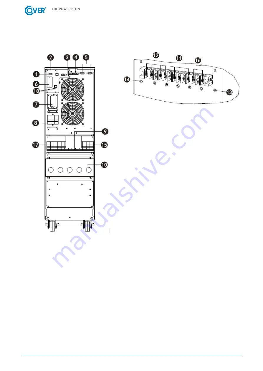
UPS rear panel
1.
RS 232 Port.
2.
USB Port.
3.
EPO port (fire protection switch connector).
4.
Parallel port (optional).
5.
Parallel port (optional).
6.
Communication card slot (SNMP).
7.
External battery socket.
8.
Rectifier power disconnect switch for UPS.
9.
Mechanical and service bypass.
10.
Power cable connection strip.
11.
Terminals for powering the UPS rectifier.
12.
Terminals for connecting load power.
13.
Ground terminal.
14.
Ground terminal.
15.
Internal bypass feeder disconnector of UPS.
16.
Bypass power supply terminals.
17.
Output disconnector.
18.
Bypass communication connector ext. EMBS.
Fig. 1 UPS COVER JR 10 - 20K
3.2.
Connection of the remote REPO switch
The UPS is equipped with an EPO port for connecting the Remote Emergency Power Off (REPO) switch.
The EPO port is configured as NC (normally closed), the activation of EPO occurs by breaking the
connection between Pin 1 and Pin 2 (removal of the jumper).
3.3.
Connecting communication to the External Service Bypass EMBS.
The UPS is equipped with an EMBS connector, enabling communication to be connected to the
External Service Bypass, in order to enable the inverter to be turned off while operating on the External
Bypass. It is an NC (normally closed) port that is activated by breaking the connection between Pin 1
and Pin 2 (removing the jumper). Activating the port turns off the inverter and blocks the possibility
of its activation.


