


W ARNING
Your
radio generates RF electromagnetic en-
ergy during transmit mode. This radio is designed
for and classified as “Occupational Use Only”,
meaning it must be used only during the course of
employment by individuals aware of the hazards,
and the ways to minimize such hazards. This radio
is NOT intended for use by the “General Population” in an uncon-
trolled environment.
This radio has been tested and complies with the FCC RF ex-
posure limits for “Occupational Use Only”. In addition, your
radio complies with the following Standards and Guidelines with
regard to RF energy and electromagnetic energy levels and eval-
uation of such levels for exposure to humans:
• FCC OET Bulletin 65 Edition 97-01 Supplement C, Evaluat-
ing Compliance with FCC Guidelines for Human Exposure to
Radio Frequency Electromagnetic Fields.
• American National Standards Institute (C95.1-1992), IEEE
Standard for Safety Levels with Respect to Human Exposure
to Radio Frequency Electromagnetic Fields, 3 kHz to 300
GHz.
• American National Standards Institute (C95.3-1992), IEEE
Recommended Practice for the Measurement of Potentially
Hazardous Electromagnetic Fields– RF and Microwave.
• The following accessories are authorized for use with this
product. Use of accessories other than those specified may
result in RF exposure levels exceeding the FCC requirements
for wireless RF exposure.; Belt Clip
,
Rechargeable
Li-Ion Battery Pack,
Charger.
CAU TION
To ensure that your expose to RF electromag-
netic energy is within the FCC allowable lim-
its for occupational use, always adhere to the
following guidelines:
•
DO NOT
operate the radio without a proper antenna at-
tached, as this may damaged the radio and may also exceed
FCC RF exposure limits. A proper antenna is the antenna
supplied with this radio
or antenna specifically
authorized for use with this radio.
•
DO NOT
transmit for more than 50% of total radio use time
(“50% duty cycle”). “50% duty cycle” is also applicable to
PSTN (Public Switched Telephone Network) mode
and VOX
Mode
.Transmitting more than 50% of the time can cause FCC
RF exposure compliance requirements to be exceeded. The
radio is transmitting when the TX indicator lights red. You can
cause the radio to transmit by pressing the “PTT” switch.
•
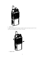
ALWAYS keep
the antenna at least 2.5 cm (1 in.) away from
the body when transmitting and only use the Icom belt-clips
listed on p. 24 when attaching the radio to your belt, etc.,
to ensure FCC RF exposure compliance requirements are
not exceeded. To provide the recipients of your transmission
the best sound quality, hold the antenna at least 5 cm (2 in.)
from your mouth, and slightly off to one side.
The information listed above provides the user with the informa-
tion needed to make him or her aware of RF exposure, and what
to do to assure that this radio operates with the FCC RF expo-
sure limits of this radio.
25
SAFETY TRAINING INFORMATION