background image

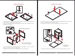
Parts and Hardware List 

Please read completely through the instructions and verify that all listed parts and hardware are present

before beginning assembly.  

Tools required: Hex wrench and open wrench (provided) and Phillips screwdriver (not provided). 

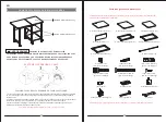
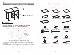
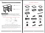
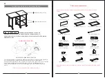
A- Large Top Panel (Qty. 1) 

            B- Small Top Panel (Qty. 1)                 C- Fixed Shelf (Qty. 2) 

D- Back Panel (Qty. 1) 

           E- Left End Frame (Qty. 1)             F- Middle End Frame (Qty. 1) 

G- Right End Frame (Qty. 1)                                                                    H- Metal Bar (Qty. 2) 

(1) Cam Lock (Qty. 8+1 extra)          (2) Cam Bolt (Qty. 8+1 extra)         (3) M6 x 12 mm Bolt (Qty. 4+1 extra) 

(4) M6 x 25 mm Bolt  


(5) M6 x 50 mm Bolt  


(6) M4 x 15 mm Screw   

(Qty. 2+1 extra)                                         (Qty. 4+1 extra)                                    (Qty. 18+1 extra)

(7) Locator Pin (Qty. 1)                          (8) Butt Hinge (Qty. 2)                     (9) Swivel Caster (Qty. 3)  

(10) Locking Caster (Qty. 3)                          Hex Wrench (Qty. 1)                          Open Wrench (Qty. 1)     


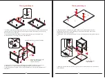
CAM LOCK SYSTEM OPERATION 

HOW THE KNOCK DOWN (KD) ASSEMBLY SYSTEM WORKS 

You are now ready to assemble the KD unit. 

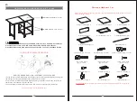
M A X IM UM   REC O M M E N D E D  W E IG H T   L O AD S

                                      THIS UNIT IS INTENDED FOR USE ONLY WITH THE MAXIMUM
WEIGHTS INDICATED. USE WITH LOAD HEAVIER THAN THE MAXIMUM

WEIGHTS INDICATED MAY RESULT IN INSTABILITY, CAUSING POSSIBLE INJURY.


MAXIMUM LOAD 200 lb. (90.7 kg)

MAXIMUM LOAD 50 lb. (22.6 kg)

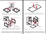
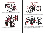
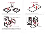
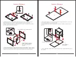
1. Screw the cam bolt into the threaded inserts on the panel. Connect both panels together; making sure 

cam bolt goes into the pre-drilled hole on the end of panel for cam lock.

2. Insert the cam lock into the pre-drilled large hole on the panel. Make sure the arrow on the face of 

cam lock faces out and points towards cam bolt.

3. Take a Phillips screwdriver and rotate the cam lock clockwise to lock the cam bolt in place.

EN

02

03

Summary of Contents for 59670831

Page 1: ...FSERLEBNIS GUTE PRODUKTE und EFFIZIENTEN SERVICE zu bieten Avec votre valuation inspirante COSTWAY continuera fournir une EXP RIENCE D ACHAT PRATIQUE des PRODUITS DE QUALIT et un SERVICE EFFICACE Con...

Page 2: ...10 Locking Caster Qty 3 Hex Wrench Qty 1 Open Wrench Qty 1 CAM LOCK SYSTEM OPERATION HOW THE KNOCK DOWN KD ASSEMBLY SYSTEM WORKS You are now ready to assemble the KD unit MAXIMUM RECOMMENDED WEIGHT L...

Page 3: ...ckets as shown 5 Combine the Top Panels A and B together by attaching two Butt Hinges 8 at the joint with six 15 mm Screws 6 per hinge using the pilot holes as a guide 6 Securely screw one Locator Pin...

Page 4: ...or assistance to lift the unit upright and position at the desired location 13 You can collapse the Large Top Panel A to save space To fold the desk lift up the Large Top Panel A a little so that you...

Page 5: ...ER ALS DIE ANGEGEBENEN MAXIMALGEWICHTE IST KANN ZU INSTABILIT T F HREN UND M GLICHE VERLETZUNGEN VERURSACHEN maximale Belastung 90 7 kg maximale Belastung 22 6 kg 1 Schrauben Sie die Nockenschraube in...

Page 6: ...us Schrauben Sie die Nockenschrauben 2 wie gezeigt fest in die Gewindebuchsen 5 Kombinieren Sie die Tischplatten A und B indem Sie zwei Sto scharniere 8 an der Verbindungsstelle mit sechs 15 mm Schrau...

Page 7: ...zuheben und an der gew nschten Stelle zu positionieren 13 Sie k nnen das gro e obere Bedienfeld A reduzieren um Platz zu sparen Um den Schreibtisch zusammenzuklappen heben Sie die gro e obere Abdeckun...

Page 8: ...AVEC LES CHARGES MAXIMALES INDIQU ES L UTILISATION AVEC UNE CHARGE PLUS LOURDE QUE LES CHARGES MAXIMALES INDIQU ES PEUT ENTRA NER UNE INSTABILIT CAUSANT DES BLESSURES VENTUELLES CHARGE MAXIMALE 90 7 k...

Page 9: ...rs le haut Vissez fermement les boulons came 2 dans les douilles filet es comme indiqu 5 Combinez les panneaux sup rieurs A et B ensemble en fixant deux charni res 8 l articulation avec six vis 6 de 1...

Page 10: ...soulever l unit en position verticale et la positionner l endroit souhait 13 Vous pouvez rabattre le grand panneau sup rieur A pour gagner de la place Pour plier le bureau soulevez un peu le grand pa...

Page 11: ...DO PARA SER UTILIZADO NICAMENTE CON LAS CARGAS M XIMAS INDICADAS EL USO CON UNA CARGA M S PESADA QUE LAS CARGAS M XIMAS INDICADAS PUEDE RESULTAR EN INESTABILIDAD CAUSANDO POSIBLES LESIONES CARGA M XIM...

Page 12: ...riba Atornille firmemente los pernos de leva 2 en los encajes roscados como se muestra 5 Combine los paneles superiores A y B juntos fijando dos bisagras 8 a la junta con seis tornillos de 15 mm 6 par...

Page 13: ...tar la unidad en posici n vertical y colocarla en el lugar deseado 13 Puede plegar el panel superior grande A para ahorrar espacio Para doblar el escritorio levante un poco el panel superior grande A...

Page 14: ...ATI AVVERTENZA UTILIZZARE QUESTO PRODOTTO SOLO QUANDO INDICATA LA CAPACIT DI CARICO MASSIMA SE SUPERA LA CAPACIT DI CARICO MASSIMA SPECIFICATA IL TAVOLO POTREBBE DIVENTARE INSTABILE E CAUSARE LESIONI...

Page 15: ...rivolti verso l alto Avvitare saldamente i bulloni a camma 2 nelle prese filettate come mostrato 5 Unire i pannelli superiori A e B fissando due cerniere di testa 8 al giunto con sei viti da 15 mm 6 p...

Page 16: ...to in posizione verticale e posizionarlo nella posizione desiderata 13 Puoi piegare il grande pannello superiore A per risparmiare spazio Per piegare il tavolo sollevare leggermente il pannello superi...

Page 17: ...NIE TEN PRODUKT JEST PRZEZNACZONY DO U YTKOWANIA MAJ C NA UWADZE MAKSYMALNE OBCI ENIA W PRZECIWNYM RAZIE MO E TO SPOWODOWA NIESTABILNO I P NIEJSZE OBRA ENIA CIA A Maksymalny ud wig 90 7 kg Maksymalny...

Page 18: ...twory by y skierowane do g ry Wkr ci mocno ruby mimo rodowe 2 w gwintowane tuleje jak pokazano na rysunku 5 Po cz g rne panele A i B razem mocuj c dwa zawiasy 8 do cze za pomoc sze ciu rub 15 mm 6 dla...

Page 19: ...ro o pomoc w podniesieniu urz dzenia do pozycji pionowej i ustawieniu w danym miejscu 13 Aby zaoszcz dzi miejsce mo na z o y du y panel g rny A Aby z o y biurko unie nieco du y panel g rny A tak aby m...

Reviews: