background image

29

MYDENS 60

COSMOGAS

5 - INSTALLATION

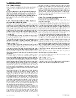
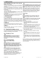
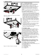
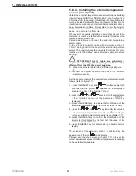
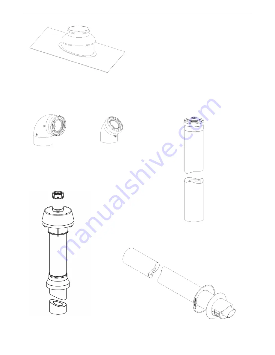
5.16.6 - “80/125PP Coaxial” System: 

accessories available

The following accessories are available on request to make 

the 80/125 coaxial fumes exhaust/air intake system:

(the number after the code is used to recall the piece in the 

following drawings) 

62617255 - N° 2 converts for pitched roofs from 5° to 25° 

extension L = 1000 mm

62617321 - N° 1 90° coaxial bend M/F PP

62617322 - N° 6 45° coaxial bend M/F PP

62617323 - N° 7 Coaxial extension L 1m PP

62617325 - N° 3 coaxial PP roof terminal

62617324 - N° 5 coaxial PP wall terminal

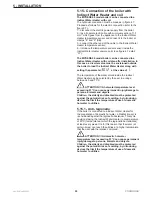
62617255

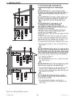
62617321

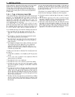
62617322

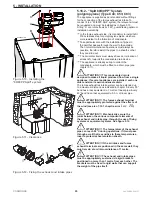
62617323

62617324

62617325

Summary of Contents for MYDENS 60

Page 1: ...62403579 R00 28 11 2013_GB INSTALLATION USE AND MAINTENANCE MANUAL MYDENS 60 GAS WALL MOUNTED CONDENSING BOILER ...

Page 2: ...1 Condensate drain 18 5 12 Safety valve 18 5 13 Water gas connections 18 5 14 Electric connections generalities 19 5 14 1 Power supply cable connection 20 5 14 2 Choice of the room thermostat chronothermostat 20 5 14 3 Connecting the room thermostat chronothermostat 20 5 14 4 Installing the external temperature sensor on request 21 5 15 Connection of the boiler with Indirect Water Heater and coil ...

Page 3: ... 18 Installer menu 45 7 19 Diagnostics 47 7 19 1 Diagnostics blocks Loc 48 7 19 2 Diagnostics errors E 50 7 19 3 Diagnostics alarms AttE 51 8 MAINTENANCE 52 8 1 General recommendations 52 8 2 Removing the casing and access to internal components 53 8 3 Removing the burner fan unit 54 8 4 Cleaning the burner and the fumes side primary heat exchanger 54 8 5 Correct positioning of the ignition and io...

Page 4: ... sensory conditions or lack of experience and knowledge unless they have been given supervision or instruction concerning use of the appliance by a person responsible for their safety This manual is an integral and essential part of the product and must be kept carefully by the user for possible future consultation If the appliance must be transferred or if you should move and leave the unit to an...

Page 5: ... without integrated pump Indoor wall mounted ecological condensing gas boiler with pre mixed burner 2 3 Manufacturer COSMOGAS srl Via L da Vinci 16 47014 Meldola FC Italia Tel 0543 498383 Fax 0543 498393 www cosmogas com info cosmogas com 2 4 Key for the symbols used ATTENTION Electric shock hazard Failure to comply with these recommendations can jeopardise the good working order of the appliance ...

Page 6: ...y heat exchanger 10 Return fitting 11 Air vent valve 12 Air intake and burned gas exhaust 13 Support attachments 14 Spark generator 15 Ignition cables 16 Fumes non return valve 17 Air inlet manifold 18 Air gas manifold 19 Gas valve 20 Access to the gas valve adjusters 21 Front casing 22 Display 23 Control board 3 MAIN COMPONENTS Figure 3 1 Boiler internal components 4 20 13 23 22 12 21 19 7 16 17 ...

Page 7: ...ating circuit pressure sensor 28 Return temperature sensor Par 1007 29 Condensate collection tank 30 Safety valve 31 Fan 32 Air gas mixing unit 33 Condensate drain siphon 34 Burner 35 Burner window 36 Left ignition electrode 37 Right ignition electrode 3 MAIN COMPONENTS Figure 3 1 Boiler internal components 25 29 24 36 37 32 31 27 28 35 26 30 33 34 02 0005 01 003 ...

Page 8: ...ess steel VRC type heat exchanger 12 Fan 13 Return temperature sensor Par 1007 14 Condensate collection siphon with sediment decanter 15 Air gas mixer 16 Pneumatic gas valve 17 Central heating circuit pressure sensor 18 Circulation pump 19 Central heating circuit flow 20 Gas inlet 21 Central heating circuit return 22 Condensate drain collector and of the safety valve 23 Central heating plant 24 Ai...

Page 9: ... water flow rate higher than the pump can supply a hydraulic separator must be positioned between the boiler and the plant see figures 4 6 and 4 7 detail 20 4 1 3 Production of domestic hot water A Indirect Water Heater must be connected for the production of domestic hot water according to the layout in figure 4 7 The temperature of the domestic hot water is adjusted following the relevant proced...

Page 10: ...figure 4 2 A modulating pump can be provided on request In this case the field of modulation detail x can be verified on the graphics in figure 4 3 4 OPERATION Figure 4 2 Residual head for MYDENS 60C with 8 metre pump standard KEY for figures 4 2 and 4 3 I II III Pump speed see figure 4 2 X Range of modulation see figure 4 3 Figure 4 3 Residual head for MYDENS 60C with modulating pump on request ...

Page 11: ...acteristic curve The MYDENS 60A boiler does not have a circulation pump To dimension this pump the designer must consider the flow resistances of the plant to be created and the flow resistances of the boiler itself To do this the flow resistances of the boiler are given in a graphical form in figure 4 4 ...

Page 12: ...L certified sample point 10 Gas inlet 11 Expansion tank 12 Microbubble separator Figure 4 6 Example of connection layout with hydraulic separator device 13 External sensor on request 14 Filter 15 Electric power supply 16 Low or high temperature heat plant 17 Plant water supply 18 Domestic cold water 19 Central heating circuit pump 20 Water disconnector 21 Air vent valve 23 Condensate neutraliser 2...

Page 13: ...d water 19 Central heating circuit pump 20 Water disconnector 21 Cut off valve 22 Non return valve 23 Central heating plant flow 24 Central heating plant return 25 Cap for sludge drain 26 Central heating plant mixing valve 27 Plant drain 28 Indirect Water Heater load pump 29 Plant load unit 30 Indirect Water Heater safety valve 31 Indirect Water Heater temperature sensor 32 Domestic hot water circ...

Page 14: ...his appliance must be installed in a location where any loss of water from the same the connections between the pipes or from the safety valve drain cannot cause damage to materials or objects below The appliance must be installed within the home or otherwise protected from atmospheric agents such as rain wind sun and especially freezing Define the room and suitable position for installation takin...

Page 15: ...from the appliance must be made with materials that resist temperatures up to 97 C and pressure of 3 bar Differently e g plastic piping the plant must be fitted with the relevant protection and safety devices Before connecting the central heating pipes wash the plant thoroughly to eliminate any waste hemp radiators casting sand etc which could damage the appliance This washing operation must also ...

Page 16: ...n extremely delicate operation not to be underestimated regarding replacement of the heat generator or new installations In certain cases the incorrect assessment of the plant water features can lead to damage of the plant and heat module A plant is almost never sealed perfectly sometimes water leaks as well as the entry of oxygen can occur Both of these phenomena are dangerous The main parameters...

Page 17: ... the relevant protection and safety devices ATTENTION when installing the boiler in a low temperature plant it is indispensable to set parameter 3015 at the value of 45 C and parameter 3016 at the value of 20 C see chapter 11 With this setting the boiler will adjust the flow to a temperature between 20 C and 45 C No adjustment from the command panel also via climatic adjustment can supply water at...

Page 18: ...ameter equal to or greater than 13 mm be installed in a way to prevent the liquid from freezing therefore pay attention to any external passings It is prohibited to drain into gutters or drainpipes to slope continuously towards the drain point avoid high points which could pressurise the pipe 5 12 Safety valve The appliance is protected against overpressures by a safety valve calibrated to 3 bar s...

Page 19: ...contacts opening distance of at least 3 mm as envisioned by the current regulations on the subject Respect the polarity between the neutral phase during connection of the appliance Make sure that the water plant and heating pipes are not used as earth points for the electric or telephone plant This piping is not suitable for this purpose moreover serious corrosion damage would occur in a very shor...

Page 20: ...nnected with the following features open closed ON OFF potential free not powered closing when there is a request for heat 24Vac 1A electrical feature 5 14 3 Connecting the room thermostat chronothermostat Install the room thermostat in a place in the house where the temperature is the most characteristic of the home and however in an area that is not subjected to repeated temperature changes away...

Page 21: ... safety voltage 24Vdc they must flow in wires different from the 230 Vac power supplies 2 connect the bipolar cable to the SE clamps in figure 5 7 3 connect the bi polar cable to the ends of the external temperature sensor Set the boiler to learn of the external temperature sensor as follows refer to figure 7 1 1 press the RESET keys and simultaneously for 5 seconds until the symbol appears on the...

Page 22: ...f the water stored inside the Indirect Water Heater can be selected by the user in a range between 40 and 70 C ATTENTION A hot water temperature level exceeding 51 C can cause permanent injury damage to persons animals and objects Children the elderly and disabled must be protected against the potential risks of scalding by introducing devices that limit the temperature of use of domestic hot wate...

Page 23: ...tures plate affixed to the boiler also under the type heading The symbols used to define type of exhaust is given below B23 separated with intake in room and exhaust through wall or roof ATTENTION If the appliance is installed with the B23 type exhaust it will take in air for combustion from the surrounding environment Therefore all precautions must be taken regarding ventilation of the rooms whic...

Page 24: ...lso be obtained from an adjacent room as long as it has direct ventilation in compliance with the previous points in the room to be ventilated only appliances fitted to exhaust pipes are installed the adjacent room is not a bedroom the adjacent room is not a common part of the building the adjacent room is not an environment with fire hazard such as a hangars garages combustible materials warehous...

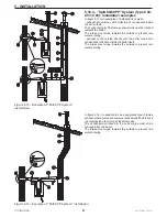
Page 25: ...ral appliances are installed each one must envision its own condensate drain The fumes exhaust air intake system can be extended up to a maximum distance as indicated in chapter 9 Every 90 bend has a loss equivalent to 1 metre of linear pipe Every 45 bend has a loss equivalent to 0 5 m of linear pipe ATTENTION The fumes exhaust terminal must be appropriately protected against the effects of the wi...

Page 26: ...number after the code is used to recall the piece in the following drawings 62617306 N 10 PP coaxial roof terminal 62617244 N 12 90 bend M F PP 62617255 N 29 converts for pitched roofs from 15 up to 25 62617236 N 11 extension M F PP 62617249 N 18 anti slip bands for extensions PP 62617240 N N 14 flexible hose M F PP L 20m 62617241 N 16 spacer for flexible hose 62617238 N 17 telescopic joint PP 626...

Page 27: ...directly with the boiler pipes with condensate collection inside the boiler itself The intake must slope towards the outside to prevent rain water entering In figure 5 14 it is possible to see a separated type of fumes exhaust where fumes exhaust was realised with flexible hose in polypropylene for piping of technical cells The condensate produced in the vertical pipe must all be conveyed into the...

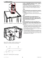
Page 28: ...gid walls that can support the weight of the pipe itself ATTENTION Once these operations have been performed check that the exhaust intake terminal is exposed to the outdoors with the tolerances given in figure 5 18 Take particular care with the installation of pipes in the part that passes through the wall to the outside The normal maintenance operations must always be possible therefore install ...

Page 29: ...tem the number after the code is used to recall the piece in the following drawings 62617255 N 2 converts for pitched roofs from 5 to 25 extension L 1000 mm 62617321 N 1 90 coaxial bend M F PP 62617322 N 6 45 coaxial bend M F PP 62617323 N 7 Coaxial extension L 1m PP 62617325 N 3 coaxial PP roof terminal 62617324 N 5 coaxial PP wall terminal 62617255 62617321 62617322 62617323 62617324 62617325 ...
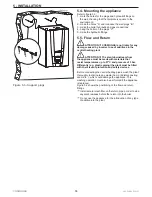
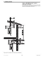
Page 30: ...tem installation examples When a coaxial exhaust is made see figure 5 18 both vertical and horizontal the exhaust pipe slope upwards in a way to make the condensate flow into the boiler Figure 5 18 Examples of coaxial pipe installation 5 INSTALLATION ...

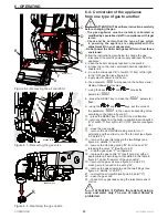
Page 31: ...a rubber hose into the opening S and the other end of the hose into the funnel 3 use the funnel to slowly pour about 200 cm3 a glass of water 4 re mount everything in reverse order 6 OPERATING Figure 6 1 Filling the condensate drain siphon ATTENTION If the boiler remains off for more than 3 months the siphon must be filled again as explained above 6 1 3 Filling the central heating plant If the wor...

Page 32: ...ion is connected ATTENTION If you smell gas A Do not switch on any electric device telephone included or any object that can cause sparks B Immediately open doors and windows causing a current of air that quickly cleans the gas from the room C From another room or from a neighbour s immediately call a professionally qualified technician or the gas supply company Call the Fire Service if the former...

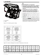
Page 33: ...ording to the table in figure 6 7 10 press the RESET key to confirm the modification 11 remove voltage from the boiler re position the microswitch B of switch A from right to left in OFF position see figure 6 5 12 close the gas supply 13 remove the air manifold making sure to turn it externally and then slide it out of the fan inlet see figure 6 2 detail C 15 remove the gas inlet pipe via the two ...

Page 34: ...identified the old state of adjustment apply the sticker onto the front casing of the boiler see figure 6 6 certifying the appliance s new state of adjustment as follows apply label B if the boiler has been converted from methane to LPG apply label A if the boiler has been converted from LPG to methane A Microswitch B Switch Figure 6 5 Positioning electric bridge A B 020002 01 043 ON OFF 6 OPERATI...

Page 35: ...wing the procedure in chapter 8 2 3 loosen the pressure point A see figure 6 8 4 connect to a manometer with resolution of at least 0 1 mbar 1 mmH2O 5 open the gas cock 6 check that the pressure does not exceed the value given in the table in chapter 9 under gas supply maximum pressure 7 make sure that any cocks and thermostatic valves downstream from the central heating circuit are open ATTENTION...

Page 36: ...oint and tube F to the positive pressure point 11 close the casing B in figure 8 1 It is indispensable to have a reliable measurement 12 switch the boiler on 13 press the and RESET keys simultaneously for more than 5 seconds to enter the installer menu confirmed by the appearance of the icon on the display 14 using the and keys access the parameter 2010 15 press the RESET key to enter the paramete...

Page 37: ...imum power If the value measured is offset from the value read it must be taken back within the value given in the table in figure 6 7 proceeding as follows a turn screw A clockwise as in figure 6 14 to decrease the level of CO2 b turn screw A anti clockwise as in figure 6 14 to increase the level of CO2 9 Once the check has been completed seal the screw A in figure 6 14 with red pain or similar s...

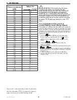
Page 38: ...e carried out setting parameter 2010 previously referred to at the rEg value 6 9 Adjustment of the power in central heating mode Range Rated This appliance is designed and type approved to adapt the maximum heating power to the effective necessity of the plant as per calculation To do this and to use the boiler s potentiality to its best it is recommended to set the maximum power in central heatin...

Page 39: ... sensor Q Boiler blocked see chapters 7 19 1 and 7 19 2 for the diagnostics R Key for increasing the domestic hot water temperature and to scroll and change the value of the parameters S Key for reducing the domestic hot water temperature and to scroll and change the value of the parameters T On Off switch 7 1 Controlling cock opening The gas cock must be open Any valves positioned on the flow and...

Page 40: ...nds water to the plant is switched on and off by the room thermostat This can be noted because the indicator flashes when the pump is on while it remains on with a fixed light when the pump is off The pump may initially make a noise This is due to the presence of residual air in the hydraulic plant which will disappear quickly without any intervention For rational use of the boiler it is recommend...

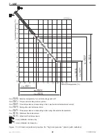
Page 41: ...ostat makes the appropriate corrections to the room temperature by switching the boiler pump on and off large plants with radiant panels low temperature where each area is controlled by its own room thermostat and the boiler pump is stopped only when all area thermostats are satisfied envision the appropriate electric plant 7 11 2 Climatic adjustment precautions during adjustment To set the flow t...

Page 42: ...t external temperature winter Par 2022 Flow temperature corresponding to the project external temperature winter Par 2023 Spring like external temperature Par 2024 Flow temperature corresponding to the spring like external temperature Par 3016 Minimum flow temperature Par 3015 Maximum flow temperature Line parallelism increase key Line parallelism decrease key 7 USE Par 2021 Par 2023 Par 2020 Par ...

Page 43: ...the appliance improve the comfort generated and increase energy saving timings have been introduced during operation These timings are Pump post circulation every time that the room thermostat determines the end of the central heating service the pump continues to operate for 3 minutes Central heating delay every time that the domestic hot water service finishes before reactivation of the central ...

Page 44: ... mode ON OFF 1011 Status of the D H W side diverter valve ON in D H W mode OFF in central heating mode ON OFF 1012 Central heating flow temperature calculated via the external sensor C 1013 Status of the room thermostat contact OPEN no central heating request CLOSED presence of central heating request OPEN CLO SED 1014 Fumes temperature safety sensor C 1040 Current rotation speed of the fan rpm 10...

Page 45: ...ed automatically Any data variation that is not confirmed with the RESET key will be lost ATTENTION Any variation to the parameters must be noted in the Customised values column present in the following table in order to facilitate the eventual replacement of the command and control board The following parameters can be changed or queried in this menu 7 USE Parameter Description of the parameter M...

Page 46: ...sec From 10 to 900 180 2043 Protection against frequent switch on in central heating mode temperature differential C From 0 to 20 16 2060 Domestic hot water minimum power level From 1 to 50 1 2061 Domestic hot water maximum power level From 1 to 100 100 2062 Post circulation in domestic hot water mode sec From 10 to 900 120 2063 Maximum time for charging Indirect Water Heater min From 0 to 60 60 2...

Page 47: ...ot water service on and active Domestic hot water temperature C Fixed on Central heating service on but not active On flashing Central heating service on and active Central heating temperature C Loc Boiler blocked To reset press RESET If the block occurs frequently contact a professionally qualified technician Block code see chapter 7 19 1 for decode Err Boiler in error mode Functioning can only b...

Page 48: ...lace the command and control board Loc 4 Boiler in error mode for more than 20 hours Control the last error displayed in the board Operate according to the last error displayed Loc 5 Fan out of speed for more than 60 seconds Control it is powered at 300 Vdc If the fan is powered it must be replaced differently replace the board Loc 6 Software error inside the command board Replace the command and ...

Page 49: ...central heating circuit flow rate is not too low If one of the two or both sensors do not have correct values they must be replaced If the temperature difference between U1 and U8 is greater than 30 C at maximum power and the flow rate of the central heating circuit is low the flow rate must be increased Loc 24 The two fumes sensors measure the different temperatures for more than 60 seconds Check...

Page 50: ...ware error inside the command board Replace the command and control board Err 44 Flame detected in a moment when it should not be present Replace the gas valve Err 45 Central heating water low pressure Check the pressure switch calibration pressure FILL must appear when the pressure drops below 0 6 bar check that there are no water leaks from the central heating plant If the pressure switch is not...

Page 51: ...ace the command and control board Err 58 Flow sensor circuit 2 1005 in short circuit condition Check that the electric resistance of the sensor matches the graphics in chapter 8 17 Check the electric cables for connection between the sensor and the command board If the electric resistance does not match replace it The electric circuit must be repaired if it is damaged Without either of the two pre...

Page 52: ...activate the call service Per attivare il servizio di chiamata procedere come di seguito 1 access the Installer menu see chapter 7 18 and set parameter 2080 on 0n 2 access parameter 2081 and set the boiler operating days which must pass between one call and the next The call will be completed with SEr on the display To remove the wording SEr and renew the call period operate as follows 1 access th...

Page 53: ...n the screws A 2 pull the lower part of the front piece B towards the front and then slide it out upwards until it is released from the guides C To access the command and control board 1 turn the command board D towards the front 2 open the commands board D by operating on closure G To access the electric connections board 1 turn the command board D towards the front 2 slide lid E out by operating...

Page 54: ...D 020005 01 008 8 4 Cleaning the burner and the fumes side primary heat exchanger To correctly clean the burner and body of the heat exchanger fumes side proceed as follows refer to figure 8 2 when not differently specified 1 access the internal components following chapter 8 2 2 remove the burner unit following chapter 8 3 3 pass a cylindrical brush with plastic bristles inside the combustion cha...

Page 55: ...owing chapter 8 2 3 remove the burner unit following chapter 8 3 4 loosen the fittings B and C 5 extract the flow meter A paying attention to the direction of the flow as per arrow printed on the flow meter 6 replace the flow meter 7 during mounting make sure the flow meter is positioned correctly step highlighted in point 4 8 7 Removing the safety valve The safety valve detail A in figure 8 5 pro...

Page 56: ...ater inside the siphon to be removed 5 slide the support C outwards from the holding support 6 slide the tank D downwards paying attention to the fact that it is full of condensate water and this could escape 7 extract the siphon outwards see figure 8 7 paying attention to disconnect the collection pipes of the water coming from the upper part of the appliance and from the air vent valve 8 clean t...

Page 57: ... access the internal components of the appliance following chapter 8 2 3 disconnect the connection cable from sensor A 4 extract the drive bar B as indicated in the figure 5 slide out and extract the pressure sensor A from the fitting C as indicated in the figure 6 replace the sensor restoring the connections as previously 8 10 Replacing the pump motor If the circulation pump must be replaced oper...

Page 58: ...pter 7 18 and set it on FAn To go back to normal operating conditions set parameter 2010 again to 0FF 8 14 Minimum and maximum power Appliance operation can be forced to its own minimum maximum adjusted or ignition power Proceed as follows 1 make sure that any cocks and thermostatic valves downstream from the central heating circuit are open ATTENTION During forcing of the delivery temperature it ...

Page 59: ...nd also check in addition to CO2 the combustion efficiency which must be over 96 Figure 8 12 Water sensors curve Figure 8 13 External temperature sensor curve 8 MAINTENANCE 8 17 Water temperature measurement sensors The temperature sensors are positioned on the boiler s exchanger body The electric resistance existing between the two contacts of the sensor must correspond with that stated in figure...

Page 60: ...mple above to identify the correct follow on of the cables in the next page 8 MAINTENANCE 1001 Boiler body sensor 1 1002 SB Indirect water heater sensor 1004 External temperature sensor 1005 Boiler body sensor 2 1006 Fumes sensor 1007 Return sensor 1014 Fumes safety sensor CM Boiler control unit and flame control DSP Display EA Ignition electrode ER Detection electrode F PWM Fan F BCU 5A fuse ...

Page 61: ...4 pin Molex connector J26 4 pin Molex connector J3 12 pin Molex connector J4 4 pin Stelvio connector J5 16 pin Molex connector J6 14 pin Molex connector J7 10 pin Molex connector J9 4 pin Molex connector PB Indirect Water Heater pump PS Central heating circuit pressure sensor SDC Connection board TA Room thermostat TU Flow meter water flow rate measuring device VG1 Gas Valve ...

Page 62: ...62 MYDENS 60 COSMOGAS 8 20 Multi wire wiring diagram Figure 8 15 Multi wire wiring diagram Key see key figure 8 14 8 MAINTENANCE ...

Page 63: ...63 MYDENS 60 COSMOGAS 8 MAINTENANCE ...

Page 64: ...osses at the chimney burner on 80 60 1 1 Losses at the chimney burner on at minimum power 0 5 0 5 Losses at the chimney burner off 0 1 0 1 Losses at the casing burner on 0 1 0 1 Losses at the casing burner off 0 05 0 05 Losses at zero load 0 05 0 05 Generator average test temperature 80 60 C 70 70 Generator average test temperature 40 30 C 35 35 Return temperature in test conditions 80 60 C 60 60 ...

Page 65: ...0 10 Fumes pipe max length split 60 m N A N A Fumes pipe diameter coaxial 80 125 mm 80 125 80 125 Fumes pipe max length coaxial 80 125 m 10 10 Equivalent length of a bend m 1 1 Weighted CO 0 O2 with natural gas ppm 15 15 Weighted NOx 0 O2 with natural gas class 5 EN 483 and 297 ppm 15 15 CO2 at natural gas minimum maximum power Metano 8 5 9 0 8 5 9 0 CO2 at LP gas minimum maximum power GPL 10 0 10...

Page 66: ...or a time in seconds indicated by the number Press and release the key Press and release the key Parameters that can be displayed in the normal operational conditions see chapter 7 19 User menu parameters see chapter 7 17 Installer menu parameters see chapter 7 18 Installer menu parameters see chapter 7 18 User menu access see chapter 7 17 Installer menu access see chapter 7 18 Return to normal op...

Page 67: ...alue Customised values 3002 Selection type From 50 to 55 See figure 6 7 3012 Domestic hot water operating mode 0 No domestic hot water 1 Indirect Water Heater with temperature sensor 2 Indirect Water Heater with thermostat 3 Instantaneous with flow switch 4 Microaccumulation with two sensors 5 Instantaneous with turbine model P 5 model B 1 model C 0 model A 0 3013 Plant load automatic valve 0 Valv...

Page 68: ...able in chapter 9 under CE type certificate PIN and meeting that required by the Directives Gas Appliances 2009 142 CE former 90 396 CEE Efficiency 92 42 CEE Low Voltage 2006 95 CE Electromagnetic Compatibility 2004 108 CEE the warranty number corresponds to the serial number This declaration is issued for that established by the above mentioned Directives Meldola FC ITALY Date of manufacture MANU...

Page 69: ...FACTURE listed in the CE declaration of conformity was subjected to the hydraulic test of 6 bar with positive outcome Operating on gaseous fuel type G20 G25 G30 G31 To be completed by the installer once found the type of gas appliance operating Thermal power refers to the PCI heat input Q 57 8 kW Useful heat P 56 1 kW Maximum pressure operating 4 Bar Test pressure 6 Bar Set pressure of the safety ...

Page 70: ...g and to validate the warranty To validate the warranty it will be the technician perform all the controls of the appliance in accordance with instructions contained in this manual and the regulations in force national and or local The list of authorised technicians is found attached to the instruction manual or can be found in the Yellow Pages under Gas boiler The technician will take the warrant...

Page 71: ......

Page 72: ...COSMOGAS s r l Via L da Vinci 16 47014 MELDOLA FC ITALY info cosmogas com www cosmogas com ...

Reviews: