STANDARD RECOMMENDED PROCEDURE 003-333 | ISSUE 9 |
March
2012 | PAGE 4 OF 6
4.3. rack-mounting with Front
importAnt:
Make sure there is adequate space above and
below the unit to route cables. Do not violate
the minimum bend radius for any cable being
installed. If you are installing a pass-through kit,
maintain between 0.8 to 2 inches between the two
units.
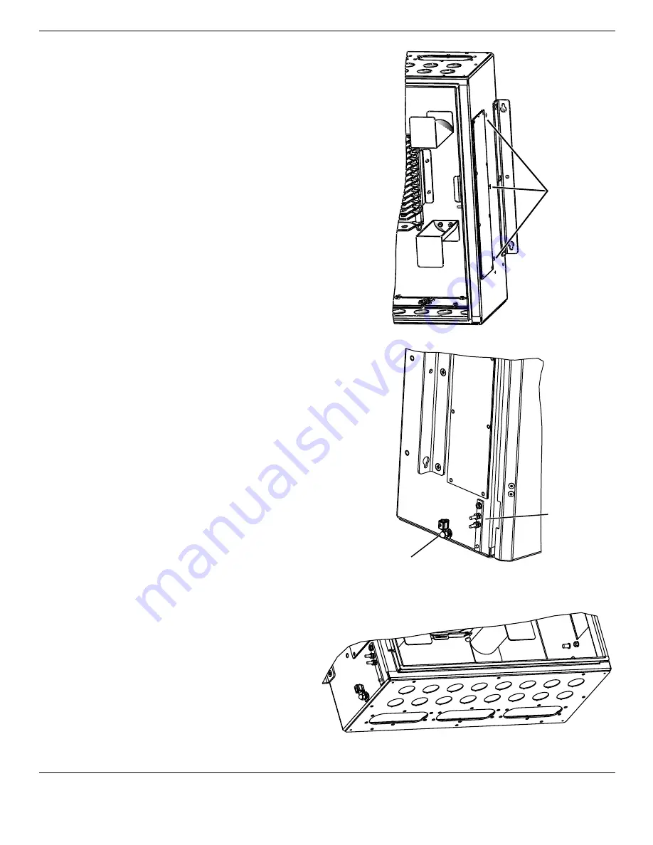
Determine the location of the enclosure in the utility rack.
If mounting the cabinet into the 23-inch rack with frontal
projection, use the two OSE mounting brackets as they
were factory-installed on each side of the cabinet.
(optionAL: recessed mounting)
If mounting the
cabinet into the 23-inch rack with recessed projection,
remove the mounting brackets and reattach them in the
alternate location shown.
step 1:
Insert two screws in the top two position on
either side of the 23-inch rack where the OSE
bracket is to be mounted.
step 2:
Leave a
1
/
8
-inch gap between the rack and the
screw head to hang the unit.
step 3:
Lift the cabinet into position on the rack and
hang the cabinet on these bolts through
the upper holes in the mounting brackets.
Tighten the screws against the brackets.
step 4:
Install the lower mounting screws and tighten
them against the mounting brackets.
5.
GroundinG
Locate the external ground locations shown. Ground
unit per local practices.
6.
CAbLe prepArAtion
note:
cable-entry hardware kits are purchased separately.
Follow the instructions provided with the
kit. Select the appropriate cable-entry
hardware for the cable being installed.
•
ose-CbL-34 through -39:
Liquid-tight
cord connectors for most cable types.
Includes central member strain-relief
capability.
•
ose-A288-sCr-36 or -38:
Liquid-
tight cord connectors for cut cable
applications and split grommet for mid-
span applications. Includes one breakout
tray. No central member strain-relief
capability.
Alternate
Bracket
Location
for
Recessed
Mounting
TPA-4081
Bare
Ground
Wire
Two-hole
Lug Ground
TPA-4083
TPA-4084


