


I ns t al l at i o n C MA - XX X- A E N
P a ge 3 8
Draft
4.7
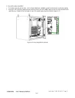
Power Connections
The MRU power connections depend on the type of power module (AC or DC). The power entry module (PEM) is located on
the bottom right of the chassis front.
•
Refer to section
4.7.1 for AC model power connections
•
Refer to section
4.7.2 for DC model power connections
4.7.1
AC Models
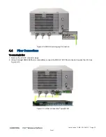
Using the provided AC power cable only, simply connect the MRU AC power connector to the AC power source.
Note the following:
•
Power input: 100-240 VAC / 50-60 Hz
•
Power consumption: 360 W (max.)
•
Maximum AC current consumption: 5A
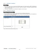
Figure
4-20. MRU AC Model Power Connector
4.7.2
DC Models
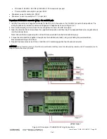
DC models include two types of terminal block connectors:
•
CLASS 2 (default) – two eight pin terminal block connectors for remote feed (see section
4.7.2.1).
•
CLASS 1 – one two pin terminal block for local plant feed. To use CLASS1 user must change default connector mode
from CLASS 2 to CLASS 1 (see section
4.7.2.2).
4.7.2.1
CLASS2 Connector (Remote Feed)
Note the following:
•
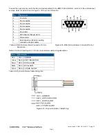
The CLASS2 DC connector supports the following wire pairs (refer to Figure
4-21):
•
One pair for each installed PAM (up to five pairs)
•
One pair for OPTM + FAM
•
One reserved pair (RSV) for future use
•
DC CLASS2 connector specs:
•
Supported wire AWG:
o
Conductor cross-section, solid (AWG/mm²): 30~12 / 0.2~2.5
o
Conductor cross-section, flexible (AWG/ mm²): 30~12 / 0.2~2.5
•
Wire strip length: 9~10 mm
•
DC Power input:
•
DC class 1: 48 VDC (40-60 VDC) 9 A max


