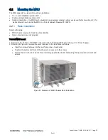


I ns t al l at i o n C MA - XX X- A E N
P a ge 3 7
Draft
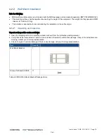
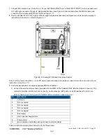
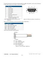
Connect the open wire dry contact cable (ordered separately) to the MRU ‘External Alarms’ port and to the external input
sources. Refer to Table
4-8 and to Figure
4-18 for pin out information.
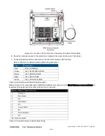
Pin
Description
1
Common
2
Not connected
3
Not connected
4
Not connected
5
Not connected
6
Door alarm
7
HEX (heat exchange) alarm
8
Future alarm
9
Exist indication (indicates existing
connection of alarm cable)
Table
4-8. MRU External Alarm Connector Pin Out
Description
Figure
4-18. MRU External Alarms Connector Pin Out
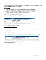
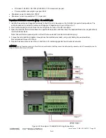
Refer to Table
4-9 and Figure
4-19 for dry contact alarms cable wiring description.
Color
Description
Red
+48 V_COMMON
Green
N48 V_EXIST INDICATION
Brown
N48 V_DOOR ALARM
Black
N48 V_HEX ALARM
White
N48 V_FUTURE ALARM
Table
4-9. Dry Contact Alarm Cable Wiring Info
Figure
4-19. Dry Contact Alarm Cable Wiring


