


Technical Support Manual – 05/2018 Rel. 2.1.3
Page 5
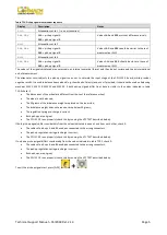
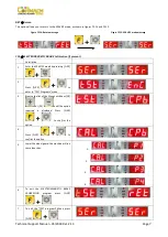
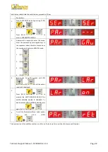
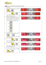
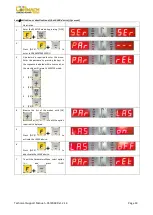
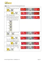
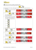
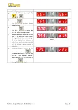
Table T2.3: Pick-up signal measurement sequence
Display
Description
Notes
Att1
Attenuation set to 1 (i.e. no attenuation)
AAA BBB
AAA = pick-up signal A
BBB = pick-up signal B
Values AAA and BBB must not differ excessively.
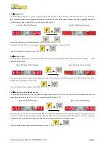
Att2
Attenuation set to 2
AAA BBB
AAA = pick-up signal A
BBB = pick-up signal B
Values AAA and BBB should be similar to those of
measurement Att1
Att4
Attenuation set to 4
AAA BBB
AAA = pick-up signal A
BBB = pick-up signal B
Values AAA and BBB should be close to those of
measurement Att1
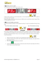
The values of the signals displayed are expressed in an internal numerical format and they do not correspond to any international
unit of measurement.
The attenuator circuit adjusts the pick-up signals so as not to saturate the input stage of the CPU-C1C.X board, which provides
negative results. It is used to balance heavy wheels (e.g. the wheels of a lorry) and, even if provided, it should not be used on balancing
machines MEC 5, MEC 10, MEC 15 and MEC 20. If both pick-up signals differ from, but are similar to the values indicated in table
T10.2 check if:
•
The dimensions of the wheel are different from those of the reference wheel;
•
The wheel is not balanced;
•
The 50 grams of the imbalance weight are placed on the inner side;
•
The imbalance weight does not exceed or drop below 50 grams;
•
The regulation spring pre-charge is correct;
•
Both pick-ups are original;
•
The CPU-C1C.X runs properly (check this by running the VFC TEST described below).
If both pick-up signals differ considerably from the values indicated in annex 1 and from each other, check if:
•
The cables of pick-ups A and B have been connected to the wrong connectors;
•
The pick-up regulation spring pre-charge is correct;
•
The CPU-C1X.X runs properly (check this by running the VFC TEST described below).
If only one pick-up signal differs considerably from the values indicated in table T10.2, check if:
•
The cables of pick-ups A and B have been connected to the wrong connectors;
•
The pick-up regulation spring pre-charge is correct;
•
Both pick-ups are original;
•
The CPU-C1C.X runs properly (check this by running the VFC TEST described below).
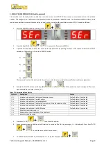
To exit the pick-up signals test, press [F+P9]
.
Summary of Contents for MEC 10
Page 1: ...WHEEL BALANCERS MEC 5 MEC 10 MEC 15 MEC 20 TECHNICAL SUPPORT MANUAL UK...
Page 2: ......
Page 38: ......