


Technical Support Manual – 05/2018 Rel. 2.1.3
Page 32
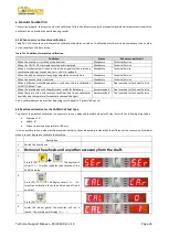
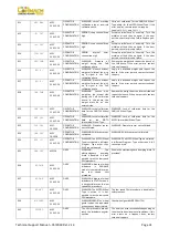
043
NO VRT
MEC
5-10-15-20
OPERATOR
CONFIRMATION
WARNING: The flange for
motorbikes was not exactly
vertical when [P8] Start was
pressed during the MOTO
Cal2 and Cal3 calibration
phases.
Put the flange for motorbikes exactly vertical
(and with the CAL reference on the upper part)
then press [P8] Start.
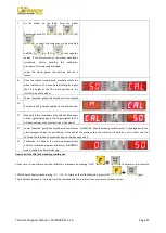
044
DIA OFF
MEC
10-15-20
OPERATOR
CONFIRMATION
WARNING: Diameter sensor
disabled or missing. It is not
possible to perform the
action required.
ONLY TECHNICAL PERSONNEL.
Make sure that the sensor is connected and
enabled.
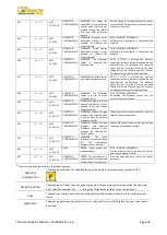
045
LAR OFF
MEC
10-15-20
OPERATOR
CONFIRMATION
WARNING: Width sensor
disabled or missing. It is not
possible to perform the
action required.
ONLY TECHNICAL PERSONNEL.
Make sure that the sensor is connected and
enabled.
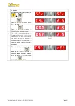
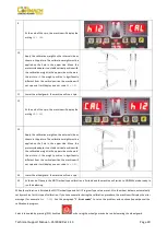
046
NO DIA
MEC
10-15-20
OPERATOR
CONFIRMATION
WARNING: The Diameter
sensor is enabled but
disconnected.
NOTE: if [F+P2] is pressed the machine
acquisition system is temporarily disabled and
operation can be continued. The disabled
status will last until the machine has been
turned off. The red LED [6] in figure F3.1 flashes
to indicate the temporary disabled status.
047
NO LAR
MEC
10-15-20
OPERATOR
CONFIRMATION
WARNING: The Width sensor
is enabled but disconnected.
NOTE: if [F+P2] is pressed the machine
acquisition system is temporarily disabled and
operation can be continued. The disabled
status will last until the machine has been
turned off. The red LED [6] in figure F3.1 flashes
to indicate the temporary disabled status.
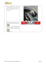
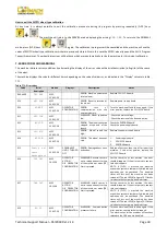
048
CAL FAR
MEC
10-15-20
OPERATOR
CONFIRMATION
WARNING: The Diameter
sensor is too far from the
calibration point.
ONLY TECHNICAL PERSONNEL.
Re-position the Diameter sensor into the
correct calibration position.
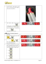
050
NO HYD
MEC
5-10-15-20
OPERATOR
CONFIRMATION
WARNING: Absence of wheel
external imbalance. It is not
possible to use the Hidden
Weight program.
051
TOO FAR
MEC
5-10-15-20
OPERATOR
CONFIRMATION
WARNING: Hidden Weights
program: the selected point
is too far from the external
imbalance position.
The point must be included up to 120° from the
external imbalance position.
052
NOT INC
MEC
5-10-15-20
OPERATOR
CONFIRMATION
WARNING: Hidden Weights
program: the external
imbalance position is not
between the selected W1
and W2 points.
Choose W1 and W2 points so that they include
the external imbalance position.
055
NO OPT
MEC
5-10-15-20
OPERATOR
CONFIRMATION
WARNING: The static
imbalance of the wheel is too
low:
the Optimization
program cannot be used.
061
BAD CMD
MEC
5-10-15-20
ONCE
ERROR: Serial control not
acknowledged.
ONLY TECHNICAL PERSONNEL.
The serial control sent to the machine has not
been acknowledged as valid.
062
BAD TAS
MEC
5-10-15-20
OPERATOR
CONFIRMATION
ERROR: The pressed key is
not permitted or an incorrect
password has been entered.
Press the permitted key or enter the correct
password.
(1)
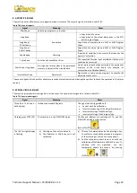
The error code can be exited in the following ways:
OPERATOR
CONFIRMATION
The machine exits the error code display when the operator presses any key (except for [P7]
).
OPERATOR ACTION
The machine exits from the error code display when the operator performs an action linked to said
error code (for example,
ERR 016
brings the Distance sensor back to the rest position).
ONCE
The machines displays once the error code and its brief description, then it returns to the previous
status.
PERMANENT
The machine permanently displays this error code until its turn-off, therefore the error code cannot
be exited.
Summary of Contents for MEC 10
Page 1: ...WHEEL BALANCERS MEC 5 MEC 10 MEC 15 MEC 20 TECHNICAL SUPPORT MANUAL UK...
Page 2: ......
Page 38: ......