XPL
These connections
MUST be made to
enable the Xenus.
Copley Controls, 20 Dan Road, Canton, MA 02021, USA
Tel: 781-828-8090
Fax: 781-828-6547
Tech Support: E-mail: [email protected], Web:
http://www.copleycontrols.co
m
Page 7 of 28
RoHS
Xenus
Plus
CANopen
Frame Ground
Signal ground
+24V Output
From 24V input on J4-3
J5
4.99k
5.1V
+HV
High Side PWM
Low Side PWM
Motor
Ouputs
4.99k
4.99k
5.1V
ENH
ENH
ENL
ENL
DIAG-ON
36V
10
+V
4.99k
LED(+)
ENL(-)
ENH(+)
Xenus Plus
STO (Safe Torque Off)
Override
Connections
ENH(-)
ENL(+)
LED(-)
2
3
1
4
5
6
7
9
8
description
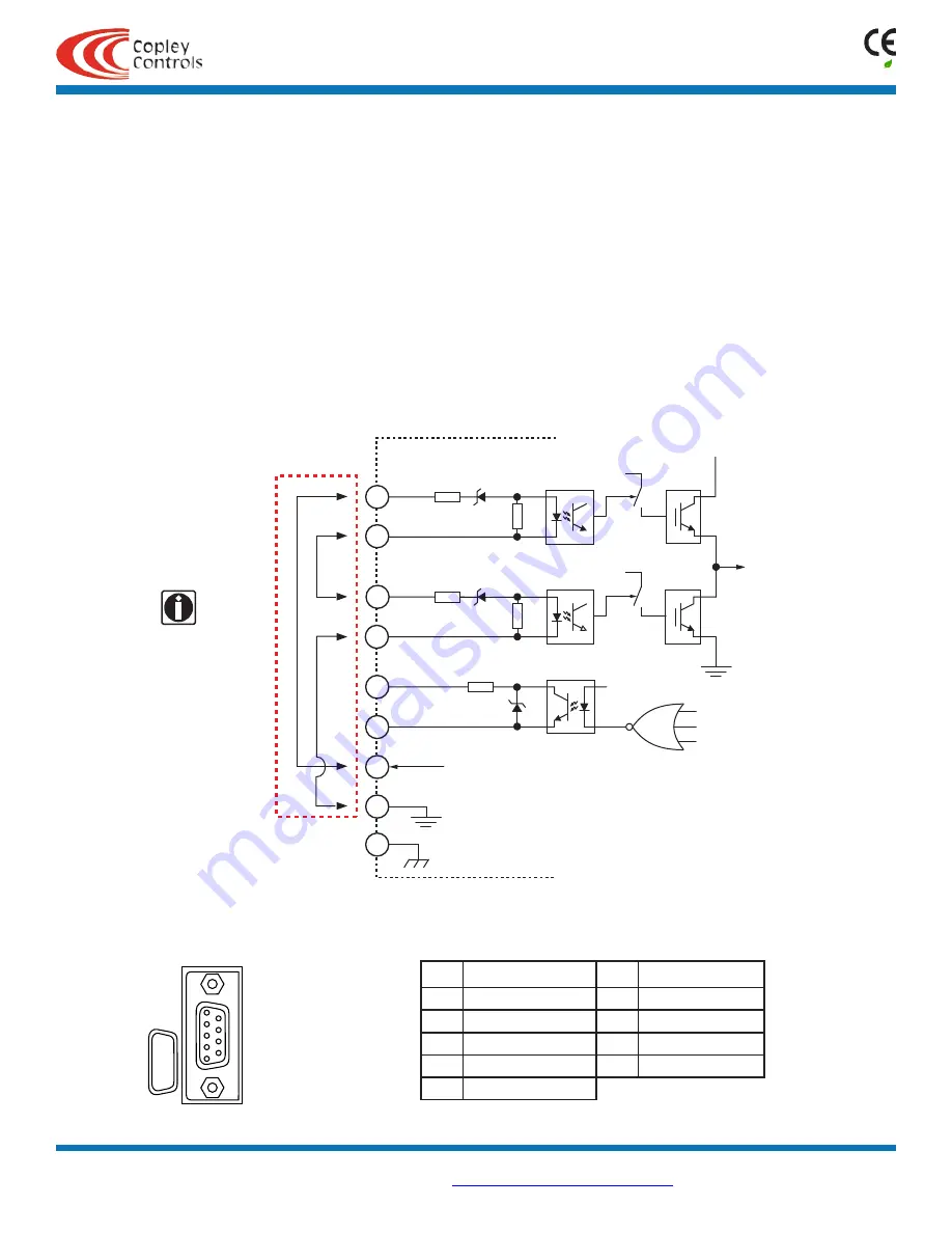
The XPL has a safety feature that is designed to provide the Safe Torque Off (STO) function as defined in IEC 61800-5-2. Two opto-couplers are
provided which, when de-energized, prevent the upper and lower devices in the PWM outputs from being operated by the digital control core. This
provides a positive OFF capability that cannot be overridden by the control firmware, or associated hardware components. When the opto-couplers are
activated (current is flowing in the input diodes), the control core will be able to control the on/off state of the PWM outputs.
SAFE TORQUE OFF (STO)
FUNCTIONAL DIAGRAM
In order for the PWM outputs of the Xenus Plus to be activated, current must be flowing through both opto-couplers that are connected to the ENH and
ENL terminals of J5, and the drive must be in an ENABLED state. The LED outputs on J5 connect an opto-coupler to an external LED and will conduct
current through the LED to light it whenever the PWM outputs can be activated, or the drive is in a diagnostic state. When the LED opto-coupler is OFF,
the drive is in a Safe state and the PWM outputs cannot be activated to drive a motor.
STO OVERRIDE
The diagram below shows connections that will energize both ENH and ENL opto-couplers.
When this is done the STO feature is defeated and control of the output PWM stage is under control of the digital control core.
If not using the STO feature, these connections must be made in order for the Xenus to be enabled.
sto connector
FUNCTIONAL DIAGRAM
pin
SIGNAL
pin
SIGNAL
1
Frame Gnd
6
Enable LED(+)
2
Safe Enable HI(+)
7
Enable LED(-)
3
Safe Enable HI(-)
8
24 Vdc Common
4
Safe Enable LO(+)
9
+24 Vdc Input
5
Safe Enable LO(-)
J5 SIGNALS
J5
1
6
9
5
S
AFETY


