background image

54

www.cooperbussmann.com/BussmannWirelessResources

Cooper Bussmann Wireless Ethernet & Device Server BU-945U-E 802.11 DSSS User Manual

3A1582Rev1.6

3.21 Configuration Examples

Setting a BU-945U-E to Factory Default Settings

Access configuration webpage on the BU-945U-E. Refer section”3.3.”

• Click on “System Tools” Menu Item

• Click on Factory Default Configuration Reset, and wait for unit to reset. While the module executes the reset sequence the OK LED will flash.

The OK LED will turn green when the reset sequence is complete.

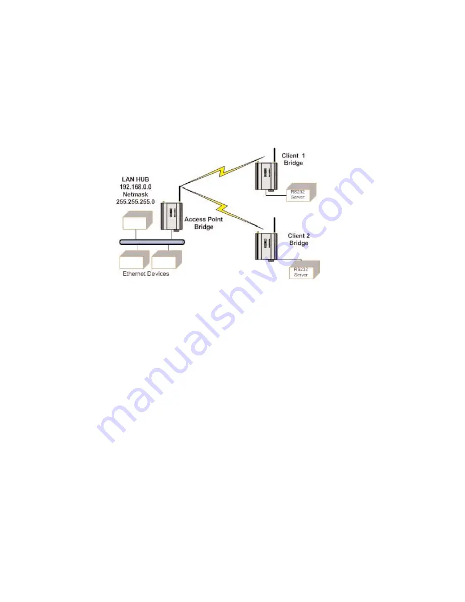
Extending a Wired Network

Access Point Configuration

• Connect straight through Ethernet cable between PC and BU-945U-E.

• Ensure configuration PC and BU-945U-E are setup to communicate on the same network

• Set DIP switch to SETUP mode.

• Power up unit, and wait for the OK LED to cease flashing.

• Adjust PC network settings

• Set Configuration PC network card with network setting of IP address 192.168.0.1, netmask 255.255.255.0

• Open configuration webpage with Internet Explorer at address 192.168.0.1XX/ where XX is the last two digits of the module’s serial number

• When prompted for password, enter default username “user” and password “user”

• Click “Network”, and select Operating Mode as Access Point.

• Select Device Mode as Bridge.

• Change the Gateway IP Address to 192.168.0.1

• Change the Ethernet and Wireless IP addresses to 192.168.0.200

• Change Ethernet and Wireless Subnet masks to 255.255.255.0

• Enter a System Address (ESSID) string

• Select the Radio Encryption required.

• Set DIP switch to RUN

• Save the changes and unit will restart with new settings.

Summary of Contents for BU-945U-E

Page 1: ...Cooper Bussmann BU 945U E 802 11 DSSS Wireless Ethernet Device Server User Manual Version 1 6 3A1582Rev1 6 Read and Retain for Future Reference ...

Page 2: ...ubject to the following two conditions 1 This device may not cause harmful interference and 2 This device must accept any interference received including interference that may cause undesired operation This device must be operated as supplied by Cooper Bussmann Any changes or modifications made to the device without the written consent of Cooper Bussmann may void the user s authority to operate th...

Page 3: ...or sources of external interference Systems should be designed to be tolerant of these operational delays 3 To avoid the risk of electrocution the aerial aerial cable serial cables and all terminals of the BU 945U E module should be electrically protected To provide maximum surge and lightning protection the module should be connected to a suitable earth and the aerial aerial cable serial cables a...

Page 4: ...GURATION 31 3 10 DNS SERVER CONFIGURATION 31 3 11 SPANNING TREE ALGORITHM REDUNDANCY 31 3 12 MULTIPLE AP REPEATER MESH NETWORK 32 Example Extending range using WDS 34 Example Roaming with WDS Access Points 35 Example Adding Redundancy 35 Example WDS Routed Network 37 WDS Connections 39 3 13 ROUTING RULES 39 3 14 WIRELESS MESSAGE FILTERING 40 MAC Address Filter Configuration 42 IP Address Filter Co...

Page 5: ... up to 100Mbit sec The module will transmit the Ethernet messages on the wireless band at rates between 1 and 54 Mbit sec 6 and 54 Mbit sec depending on model band encryption methods and radio paths 1 1 Network Topology The BU 945U E is an Ethernet device and must be configured as part of an Ethernet network Each BU 945U E must be configured as an Access Point or Sta Station Client Also needs to b...

Page 6: ...k will still work if the Client is at the LAN end An Access Point can connect to multiple Clients In this case the Access Point should be the central unit An Access Point could be used as a Repeater unit to connect two BU 945U E Clients which do not have direct reliable radio paths There is no Special repeater module any BU 945U E can be a repeater and at the same time can be connected to an Ether...

Page 7: ...thernet side A Router connects devices on different LANs The IP addresses for the Ethernet and wireless sides are different In this example the wireless link is part of LAN A with the Client unit acting as a Router between LAN A and LAN B Alternately the Access Point could be configured as a Router the wireless link is then part of LAN B If more than two routers are required within the same radio ...

Page 8: ...requires an antenna and a power supply Power the BU 945U E and make an Ethernet connection to your PC for further information on how to do this refer to section 3 3 Configuring the Unit for the first time Set the BU 945U E address settings as per section 3 3 Configuring the Unit for the first time Save the configuration the BU 945U E is now ready to use Before installing the BU 945U E bench test t...

Page 9: ... RF power permitted in your country and whether you use separate transmit and receive antennas A BU 945U E 900MHz with a single antenna 6 2 miles can be achieved in USA Canada 4W ERP and 10km in Australia New Zealand 1W ERP To achieve the maximum transmission distance the antennas should be raised above intermediate obstructions so the radio path is true line of sight The modules will operate reli...

Page 10: ...changing moving an antenna to the position of maximum signal solves this problem However where the radio path changes because the BU 945U E is mounted on moving equipment or if there is moving equipment in the area then the solution is to use two antennas Because the two connectors are separated the RF signal at each connector will be different in the presence of multi path fading The BU 945U E un...

Page 11: ...eal can be easily removed Where antennas are mounted on elevated masts the masts should be effectively earthed to avoid lightning surges For high lightning risk areas approved Cooper Bussmann surge suppression devices such as the BU CSD SMA 2500 or BU CSD N 6000 should be fitted between the module and the antenna If using non Cooper Bussmann surge suppression devices then the devices must have a T...

Page 12: ...of the transmission Ensure that the antenna mounting bracket is well connected to ground earth 2 3 Power Supply The BU 945U E module can be powered from a 9 30Vdc power supply The power supply should be rated at 1 Amp minimum The positive side of the supply must not be connected to earth The supply negative is connected to the unit case internally The DC supply may be a floating supply or negative...

Page 13: ...nnected in each multi drop network As the RS485 communication medium is shared only one of the units on the RS485 cable may send data at any one time Thus communication protocols based on the RS 485 standard require some type of arbitration RS485 is a balanced differential standard but it is recommended that shielded twisted pair cable be used to interconnect modules to reduce potential RFI It is ...

Page 14: ...ussmann com BussmannWirelessResources Cooper Bussmann Wireless Ethernet Device Server BU 945U E 802 11 DSSS User Manual 3A1582Rev1 6 Shorter runs of 485 cables may not require the termination resistors to be enabled ...

Page 15: ...transistor devices are not suitable Contact wetting current of approximately 5mA is provided to maintain reliable operation of driving relays The digital input is connected between the DIO terminal and common COM The I O circuit includes a LED indicator which is lit GREEN when the digital input is active that is when the input circuit is closed Provided the resistance of the switching device is le...

Page 16: ...he connection status to an Access Point Link status is also displayed on the Connectivity page of the web interface After the link is established data may be transferred in both directions The Access Point will act as a master unit and will control the flow of data to the Clients linked to it Clients can only transmit data to the AP to which they are connected When a Client transfers data to anoth...

Page 17: ...ive DIO Off Digital Output OFF and Input is open circuit The Ethernet RJ45 port incorporates two indication LEDs The LINK LED comes on when there is a connection on the Ethernet port and will blink off briefly when activity is detected on the Ethernet Port The 100MB LED indicates that the connection is at 100 MBit Sec The 100MB LED will be off for 10MB Sec connection Other conditions indicating a ...

Page 18: ...Channels Diagram and the Data Throughput Table below the greater the band width the greater the overall data throughput If selecting the high band width i e 20MHz you will be limited to one channel which may be more susceptible to outside interference because it spans the available 900MHz frequency range in some regions this high band width option may not even be available If selecting the lower b...

Page 19: ... 1 0 0 50 0 25 0 13 0 06 95dBm 0 5 0 25 0 13 0 06 0 03 Throughput and Repeaters It should also be noted that if using repeaters to extend the range there will be a reduction in throughput for each repeater hop The following table shows the drop in throughput for each hop and for each of the channel widths Data Throughput Based on Repeater Hops Signal Channel 20 MHz 10 MHz 5MHz 2 5MHz 1 25MHz Hops ...

Page 20: ...te of the module in SETUP position When in SETUP mode wireless operation is disabled The previous configuration remains stored in non volatile memory and will only change if a configuration parameter is modified and the change saved Do not forget to set the switch back to the RUN position and cycle power at the conclusion of configuration for resumption of normal operation Accessing Configuration ...

Page 21: ... Network Settings on your PC under Control Panel The following description is for Windows XP earlier Windows operating systems have similar settings Open Properties of Local Area Connection Select Internet Protocol TCP IP and click on Properties On the General tab enter IP address 192 168 0 1 Subnet mask 255 255 255 0 and press OK Open Internet Explorer and ensure that settings will allow you to c...

Page 22: ...you have determined the correct settings for your network you need to connect to the modem s RS 232 serial port using a straight through serial cable and a terminal package such as Hyperterminal set to 115 200 baud 8 data bits 1 stop bit no Parity Open Hyperterminal and monitor communications Set the SETUP RUN switch to the SETUP position and connect power to the modem Observe Hyperterminal and wh...

Page 23: ... Quick Start from the Main Menu and then you need to select the following parameters Quick Start Configuration Operating Mode Access Point or Client Bridge operation is assumed for Router selection go to the Network page after Quick Start Default Gateway This is the address that the device will use to forward messages to remote hosts that are not connected to any of the local bridged network Ether...

Page 24: ...tion plus separate 64bit Tx and Rx MIC Message Integrity Check keys AES Advanced Encryption Standard the most secure encryption method is also based on 128 bit encryption key and is the recommended encryption method in most applications WPA Enterprise 802 1x removes the need to manage the Pre shared Key PSK by using an external server to provide client authentication Clients that are not authorize...

Page 25: ...dress This is the unique hardware address of the BU 945U E and is assigned in the Factory The BU 945U E has two MAC addresses one for each interface Ethernet and Wireless The Ethernet MAC is the primary MAC Address IP Address The IP address of the BU 945U E on its wired Ethernet Interface port and wireless Wireless Interface port This should be set to the IP address you require If the device mode ...

Page 26: ...ame system One of the four keys may be selected as the default key and is used to encrypt transmitted messages from the configured unit A BU 945U E can receive and decrypt a message from a module that has a different default key index as long as each module has the same key configured at the same index WEP keys must be entered as pairs of hexadecimal digits separated by colons Hexadecimal digits a...

Page 27: ...bles the Supplicant to verify the identity of the RADIUS server during the authentication process Certificate Verification result Once a certificate has been loaded this text box will contain validation information for the certificate If this text is blank or contains errors the certificate is invalid Trusted CA Certificate Contents Displays the contents of the loaded certificate WPA Enterprise Au...

Page 28: ...Tree Algorithm Redundancy for more details Router Operation A router joins separate IP sub networks together The router has different IP addresses on its wired and wireless ports reflecting the different IP addresses of the separate Ethernet networks All of the devices in these separate networks identify the router by IP address as their gateway to the other network When devices on one network wis...

Page 29: ...n for low power sleeping client devices Normally set this to 1 RTS Threshold Ready to Send RTS frames can be used to help avoid radio collisions between two stations that cannot directly hear each other Any frame larger than RTS Threshold bytes will be preceded by an RTS message The default value of RTS Threshold is 2346 which effectively disables RTS signalling as this value is larger than the ma...

Page 30: ...over longer distances Default distance is 20km Save Changes Save changes to non volatile memory Changes will not take effect until module is reset Save Changes and Reset Save changes to non volatile memory and reset module Channel Selection BU 945U E 900MHz 802 11 channel selection is done by selecting the appropriate channel from the drop down list Only channels available for that region will be ...

Page 31: ...erver for a local network Name to IP address mapping are automatically updated by the built in DHCP server when it issues an IP address to a client unit For the DNS Server configuration to be effective Each DNS Client must be configured with the address of this DNS server as either the primary or secondary DNS secondary DNS is only used if there is no response from the primary DNS Normally this is...

Page 32: ...E must handle by placing it at the branch level in the network tree As a branch the BU 945U E needs only pass traffic to devices that are its leaves There is some overhead in maintaining a network utilizing the Spanning Tree Algorithm Users wishing to increase their throughput at the expense of redundancy should disable Spanning Tree The Spanning Tree Protocol can be configured on the Repeaters co...

Page 33: ...loops exist Each WDS interface may also be configured with a different encryption algorithm however each side of a single WDS link must specify the same encryption algorithm and keys Specify SSID for AP STA modes or MAC Address for Point to point mode Router IP and Subnet should be left blank unless that WDS interface is to be on a different subnet Leaving these fields blank will mean that the WDS...

Page 34: ...is shown above this page is accessible via the Repeaters link from the configuration web pages Site B is acting as an Access point for Site A and is a client to Site C likewise Site C is acting as an Access Point for Site B and a Client for Site D Since this example is a bridged network i e all devices on the same IP network and each link is using a different SSID there is no possibility of loops ...

Page 35: ...dancy In the example below 4 x Access Points A B C D form a mesh network using only WDS bridge interfaces Each of the Access Points may also have its own clients associated Each Access Point is configured with a different SSID meaning the clients associated with each Access Point are fixed Sites A B C and D can all exchange data with each other as can all of their Stations as if they were all on t...

Page 36: ...ents to Site B and to Site C Site B configuration Network Page configured as Primary Access Point Site B WDS configuration Repeaters Page configured with Virtual Station to Site C Site A WDS configuration Repeaters Page configured with two Virtual Clients to Sites B C Encryption levels and key above are shows as being different however they can be the same as in some of the earlier examples One re...

Page 37: ... WDS links to Site A C and D we show Site B s configuration below It can be seen that there are 3 entries in the WDS Connections list The first entry specifies a connection to the Access Point whose SSID is SSID_AA and that it is to be a Virtual Station interface with a separate Router IP address of 169 254 0 3 this is the address that Site B adopts for the link to Site A Note that this IP Address...

Page 38: ...g traffic to unit A can be seen to specify 192 168 0 0 as the destination address the network address of unit A because the last byte is zero this refers to a route to the network 192 168 0 X as opposed to a route to an individual host The same rule specifies the address 169 254 0 2 as the gateway address this is the WDS Router IP address that Site A has been configured with for its WDS link to Si...

Page 39: ...ble to WDS bridged connections only Select the STP option if you wish to enable the bridge Spanning Tree Protocol on this connection 3 13 Routing Rules When a BU 945U E receives an IP frame that is destined for an IP address on a different network it checks if the network address matches the network address of one of its own interfaces i e hard wired Ethernet or wireless Ethernet or WDS and forwar...

Page 40: ...d across the wireless interface to LAN A The Routing Rules configuration page can be accessed by selecting the Routing link on any of the configuration web pages Up to 30 routing rules may be added to each BU 945U E The table below summarizes the configurable parameters of a routing rule Name A name to describe the routing rule Max 32 characters Destination The destination network or host IP addre...

Page 41: ...destination address of the message If either address match then the rule is activated ARP filtering applies only to ARP request packets typically these are broadcast packets which are sourced from the Ethernet interface and destined for the wireless interface ARP requests from devices on the wireless network will always be passed to the Ethernet interface ARP response packets will always be passed...

Page 42: ...o enable the rule MAC Address Enter the desired source MAC Address Save Changes Save changes to non volatile memory Reset is required to activate Save Changes and Reset Save to non volatile memory And restart to activate changes IP Address Filter Configuration The IP filter allows can be used to permit or deny network access to specific devices through the use of Blacklists blocking of traffic tha...

Page 43: ...or ICMP Ping Save Changes Save changes to non volatile memory Reset is required to activate Save Changes and Reset Save to non volatile memory and restart to activate changes ARP Filter Configuration ARP Address Resolution Protocol is a broadcast message and is primarily used for finding a MAC address when only its IP or some other Network Layer address is known On large networks you generally ten...

Page 44: ...port A process called Proxy ARP is used to make the device visible on the network In this process the BU 945U E pretends that it holds the IP address on the network and responds on behalf of the remote device The result of this is similar to bridging for a single device with some exceptions One of these exceptions is the inability to handle name server searches of the network via this serial link ...

Page 45: ...5U E to be transferred to any other BU 945U E serial ports including the corresponding port on the same BU 945U E Serial Gateway Modbus Modbus RTU to TCP When configured as Modbus will allow a serial Modbus RTU Client Master to connect with a single Ethernet Modbus TCP Server Slave With the Modbus Function the serial data is encapsulated within a TCP IP data frame and made available on the Etherne...

Page 46: ... a number of retries specified by the configured Maximum Request Retries The Modbus TCP to RTU Gateway may be configured to operate on either the RS 232 or RS 485 port Serial Menu RS232 RS485 Serial Port Configuration RS232 Port Select the desired functionality Select either PPP Serial Gateway or Modbus TCP to RTU Data Rate The serial data rate desired Serial data rates available range from 110bps...

Page 47: ...members should use the same Multicast Group IP Address Valid Multicast IP Addresses are in the range 224 0 1 0 to 238 255 255 255 Modbus Server Port This is the Server Port of the local server that a remote client will connect to Modbus Server IP Address This is the IP Address of the local server that a remote Client will connect to RS232 RS485 Modbus TCP RTU Converter Modbus Server TCP Port Port ...

Page 48: ...ating Multicast devices 3 16 Digital Input Output The functionality of the shared Digital Input Output pin may be configured via the I O Transfer webpage As this pin is shared the Digital Input status will be ON when the Digital Output is set ON The Digital I O channel can be transferred to from another device using Modbus see section 3 15 Modbus I O Transfer or it can be configured to provide sta...

Page 49: ...ad only 4302 Serial Gateway RS232 Connection Status 4303 Serial Gateway RS485 Connection Status 4304 TCP RTU RS232 Connection Status 4305 TCP RTU RS485 Connection Status 4306 TCP RTU Modbus Server Connection Status 4307 Multicast Pipe Connection Status 4310 TCP RTU RS232 Number of Connections 4311 TCP RTU RS485 Number of Connections 4312 TCP RTU Modbus Server Number of Connections 4320 On board Di...

Page 50: ...bit registers from Modbus serial device D will be transferred to A Unit B is configured with Modbus TCP Server enabled and Device ID 1 Unit C is configured as shown above The first will write the register 4300 Local Digital Input to server IP address 192 168 0 200 Unit B Device ID 1 register 4320 Local Digital output The second mapping shows a Modbus read command of 8 Discretes starting at registe...

Page 51: ...ce the BU 945U E supports Modbus TCP Client and Server simultaneously the Modbus TCP Server for unit B above could also be enabled This would allow one or more external Modbus TCP Clients anywhere on the extended wired or wireless network to connect to unit B and monitor the status of the I O registers including the I O at units A C and D This is a very powerful and flexible feature which could fo...

Page 52: ...saction The Specified register will be set to 0 if communications is successful 0xFFFF if there is no connection to the specified server or 0xFFxx where xx is the Modbus Exception Code 3 18 Module Information Configuration Module Information Webpage Fields This configuration page is primarily for information purposes With the exception of the password the information entered here is displayed on t...

Page 53: ...he module When completed press Reset Firmware upgrade can be done locally or remotely via the radio Reset Resets the module Factory Default Configuration Loads the Factory default configuration and resets CAUTION Doing this will overwrite any current configuration 3 20 Remote Configuration Because a module configuration is viewed and changed in a web format which uses TCP IP protocol you can view ...

Page 54: ... E are setup to communicate on the same network Set DIP switch to SETUP mode Power up unit and wait for the OK LED to cease flashing Adjust PC network settings Set Configuration PC network card with network setting of IP address 192 168 0 1 netmask 255 255 255 0 Open configuration webpage with Internet Explorer at address 192 168 0 1XX where XX is the last two digits of the module s serial number ...

Page 55: ...rate Networks Together LAN A Configuration In this example network A is connected to the internet via a router at IP address 192 168 0 1 Devices on LAN A that only require access to devices on LAN A and B should have their gateway IP address set to the BU 945U E Access Point as 192 168 0 200 Devices on LAN A that must interact with devices on LAN A and B and the internet should set the internet ro...

Page 56: ...red and enter encryption keys or passphrase if necessary Set DIP switch to RUN Click on button Save to Flash and Reset Webpage will display that message indicating details are being written to flash Wait for BU 945U E to reboot before removing power Enter a System Generator String Client Configuration Perform the same configuration steps as the Access Point configuration with the following differe...

Page 57: ...s active DIO OFF Digital Output OFF and Input is open circuit The green OK LED on the front panel indicates correct operation of the unit This LED turns red on failure as described above When the OK LED turns red shutdown state is indicated On processor failure or on failure during start up diagnostics the unit shuts down and remains in shutdown until the fault is rectified During Module boot up t...

Page 58: ...updated Connectivity Parameters AID Association ID Every Client gets a unique temporary ID from the AP CHAN Channel What radio channel is being used RATE Radio Data Rate RSSI Radio Signal Strength Index Amount of received signal strength BGND Background interference level in dBms The amount of internal noise the radio is able to hear This level does not indicate external radio interference noise l...

Page 59: ...oblems with the module Note that when updating the Statistics webpage it is necessary to hold down the ctrl key while pressing the refresh button Otherwise the information will not be updated Network Traffic Analysis There are many devices and PC programs that will analyze performance of an Ethernet network Freely available programs such as Ethereal provide a simple cost effective means for more a...

Page 60: ...for this interface 5013 AP Only Wireless Adaptor wi0 Points to the starting register of the AP s Station List First interface wi0 will always start at 5200 and dynamically enter data depending on the number of STA s Remaining interfaces wi1 wi10 will be entered after wi0 data Register 5023 5033 etc will indicate starting location for each interface 5014 STA Only Wireless Adaptor wi0 RSSI BGND of R...

Page 61: ...terrupts 4518 Both Total data packet sent on the interface 4520 Both Transmit frames with antenna 1 TX RX 4522 Both Transmit frames with antenna 2 RX 4524 Both Transmitter antenna switches 4526 Both Transmitter on chip retries 4528 Both Transmit message failed due to too many retries 4530 Both Transmit frames with alternate rate 4532 Both Transmit frames with no ack marked i e broadcast multicast ...

Page 62: ...w data throughput and from this we can determine the amount of interference from the measured and calculated data throughput levels The preferred application is called Iperf which can be downloaded from http sourceforge net projects iperf See Appendix D IPerf Data Throughput Test for a detailed procedure on how to use Iperf to check radio data throughput 4 6 Utilities Ping Ping is a basic Internet...

Page 63: ...edly ping the specified node in the network to cancel use Ctrl C A good test for the network once it is first set up is to use ping repeatedly from one PC s IP address to the other PC s IP address This gives a good indication of the network s reliability and how responsive it is from point to point When you enter Ctrl C the program reports a packet sent received lost percentage ...

Page 64: ...e command ipconfig all Ipconfig Lists all of the commands and their usages available for use Arp Displays and modifies the IP to Physical address translation tables used by Address Resolution Protocol ARP Once a remote computer has been pinged this can be used to see the IP address MAC address of the remote computer It will also show any other devices on the network that it may be connected to Com...

Page 65: ...hown for the configuration below Network A Settings Client Bridge Settings IP Address 192 168 0 17 Gateway IP 192 168 2 51 Subnet Mask 255 255 255 0 Ethernet IP 192 168 2 50 Gateway IP 192 168 0 1 Subnet Mask 255 255 255 0 Wireless IP 192 168 2 50 Subnet Mask 255 255 255 0 Access Point Router Settings Network B Settings Gateway IP 192 168 0 1 IP Address 192 168 2 201 Ethernet IP 192 168 0 191 Subn...

Page 66: ...Access point client functionality Radio Transceiver Transmit Power Maximum Power Power may be limited by country specific configuration 6 24 Mb s 630mW 28 dBm 36 Mb s 400mW 26 dBm 48 Mb s 200mW 23 dBm 54 Mb s 125mW 21 dBm Channels US Canada 9 x 1 25MHz 9 x 2 5MHz 4 x 5MHz 4 x 10MHz and 2 x 20MHz See 3 2 Selecting a Channel for more channel detail Australia 4 x 1 25MHz 4 x 2 5MHz 3 x 5MHz and 1 x 1...

Page 67: ...racter text string Wireless Data Encryption WEP 64bit and 128bit WPA PSK TKIP WPA PSK AES WPA2 PSK AES WPA PSK WPA2 PSK WPA Enterprise User Configuration Via embedded web page Via RS232 commands Diagnostics LEDs Power OK Ethernet Link Activity 100mb s Radio Link RX Rx Weak Signal TX Serial RX TX Digital I O Input Output status Other RSSI measurement in dBm Connectivity Information System Log file ...

Page 68: ...ink from other devices as much as possible If necessary create a temporary separate radio network to perform the upgrade to remote modules Please refer to the Web based Upgrade section for the upgrade procedure Web Based Upgrade Web based firmware upgrade is available from the System tools page by selecting firmware upgrade Firmware upgrade is performed by uploading a patch file which is specific ...

Page 69: ...802 11 states collision avoidance method rather than collision detection must be used because the standard employs half duplex radios radios capable of transmission or reception but not both simultaneously Unlike conventional wired Ethernet nodes a WLAN station cannot detect a collision while transmitting If a collision occurs the transmitting station will not receive an ACKnowledge packet from th...

Page 70: ... program or device that transfers data to or from a computer Internet Appliance A computer that is intended primarily for Internet access is simple to set up and usually does not support installation of third party software These computers generally offer customized web browsing touch screen navigation e mail services entertainment and personal information management applications IP Internet Proto...

Page 71: ...ernet servers and data servers A server can also be combined with a hub or router Site Survey The process whereby a wireless network installer inspects a location prior to installing a wireless network Site surveys are used to identify the radio and client use properties of a facility so that access points can be optimally placed SSL Secure Sockets Layer A commonly used encryption scheme used by m...

Page 72: ... the corporate servers and database WAN Wide Area Network A communication system of connecting PCs and other computing devices across a large local regional national or international geographic area Also used to distinguish between phone based data networks and Wi Fi Phone networks are considered WANs and Wi Fi networks are considered Wireless Local Area Networks WLANs WEP Wired Equivalent Privacy...

Page 73: ...VERSION dBm to mW Conversion Watts dBm Watts dBm 10 mW 10 dB 200 mW 23 dB 13 mW 11 dB 316 mW 25 dB 16 mW 12 dB 398 mW 26 dB 20 mW 13 dB 500 mW 27 dB 25 mW 14 dB 630 mW 28 dB 32 mW 15 dB 800 mW 29 dB 40 mW 16 dB 1 0 W 30 dB 50 mW 17 dB 1 3 W 31 dB 63 mW 18 dB 1 6 W 32 dB 79 mW 19 dB 2 0 W 33 dB 100 mW 20 dB 2 5 W 34 dB 126 mW 21 dB 3 2 W 35 dB 158 mW 22 dB 4 0 W 36 dB ...

Page 74: ...orts Suitable Power Supplies for the Ethernet Modems Straight through Ethernet cables Iperf Jperf Application Installation The Application can be downloaded from the following link http sourceforge net projects iperf download and save to a location on your PC Extract to zip file to the ROOT directory on your PC i e C This folder contains the main Iperf application as well as the Jperf graphical in...

Page 75: ...d waiting for a Client connection On the Client PC open up the CMD prompt as performed on Server PC above followed by changing the directory path jperf 2 0 2 bin as performed above also This time instead of entering in Iperf s we enter in Iperf c IP address of Server PC w 65535 as seen in figure 3 Figure 3 This will run a test over the modem link to the Server PC and report back results as seen in...

Page 76: ... 19 2Kbps 7 8Kbps Table 1 In the command line for the Client mapping we established the Server IP address followed by the w 65535 w is the window size and the maximum TCPIP window size is 65535bytes Another entry that can be added is t seconds to run the test for a specific time period Example of this is in figure 5 where the same test is run for 30 seconds Figure 5 JPerf Application Jperf is a gr...

Page 77: ...Figure 7 When Jperf screen appears select Client Mode enter in IP address of the Server PC leave Port as default and press Run Iperf button The test will run again and the Bandwidth Throughput display will show results of the test Note Jperf runs using Java technology and depending on PC setup further installation of Java software may be required ...

Page 78: ...rotection and ours we want to make certain that everyone understands that there is no warranty for this free software If the software is modified by someone else and passed on we want its recipients to know that what they have is not the original so that any problems introduced by others will not reflect on the original authors reputations Finally any free program is threatened constantly by softw...

Page 79: ...f Sections 1 and 2 above provided that you also do one of the following a Accompany it with the complete corresponding machine readable source code which must be distributed under the terms of Sections 1 and 2 above on a medium customarily used for software interchange or b Accompany it with a written offer valid for at least three years to give any third party for a charge no more than your cost ...

Page 80: ...ces the Program under this License may add an explicit geographical distribution limitation excluding those countries so that distribution is permitted only in or among countries not thus excluded In such case this License incorporates the limitation as if written in the body of this License 9 The Free Software Foundation may publish revised and or new versions of the General Public License from t...

Page 81: ...www cooperbussmann com BussmannWirelessResources Cooper Bussmann Wireless Ethernet Device Server BU 945U E 802 11 DSSS User Manual 81 3A1582Rev1 6 Notes ...

Page 82: ... assistance is available to all customers Staffed by degreed engineers this application support is available Monday Friday 8 00 a m 5 00 p m CT Contact s Phone 636 527 1270 s Fax 636 527 1607 s E mail fusetech cooperindustries com s Live Chat www cooperbussmann com Online Resources Visit www cooperbussmann com for the following resources s Product search cross reference s Product technical materia...

Reviews: