


50
www.cooperbussmann.com/BussmannWirelessResources
Cooper Bussmann Wireless Ethernet & Device Server BU-945U-E 802.11 DSSS User Manual
3A1582Rev1.6
Modbus RTU (serial) Master functionality is achieved by combining the Modbus TCP Client (Master) and Modbus TCP to RTU Gateway. Simply
specify a Modbus TCP Client (Master) connection to a Modbus TCP Server where the server is the address of any BU-945U-E with Modbus TCP to
RTU Gateway enabled. Care should be taken to ensure that the Device ID (i.e., Modbus Address) of the serial device is different to the Device ID of
the onboard Modbus TCP Server of the BU-945U-E that the serial device is connected to.
The BU-945U-E provides a configurable option to automatically reset the value of the onboard I/O registers to zero in the event of a
communications failure. If a valid Modbus transaction directed to/from a given register has not been completed for longer than a configurable
timeout, then the value of that register will be reset to zero.
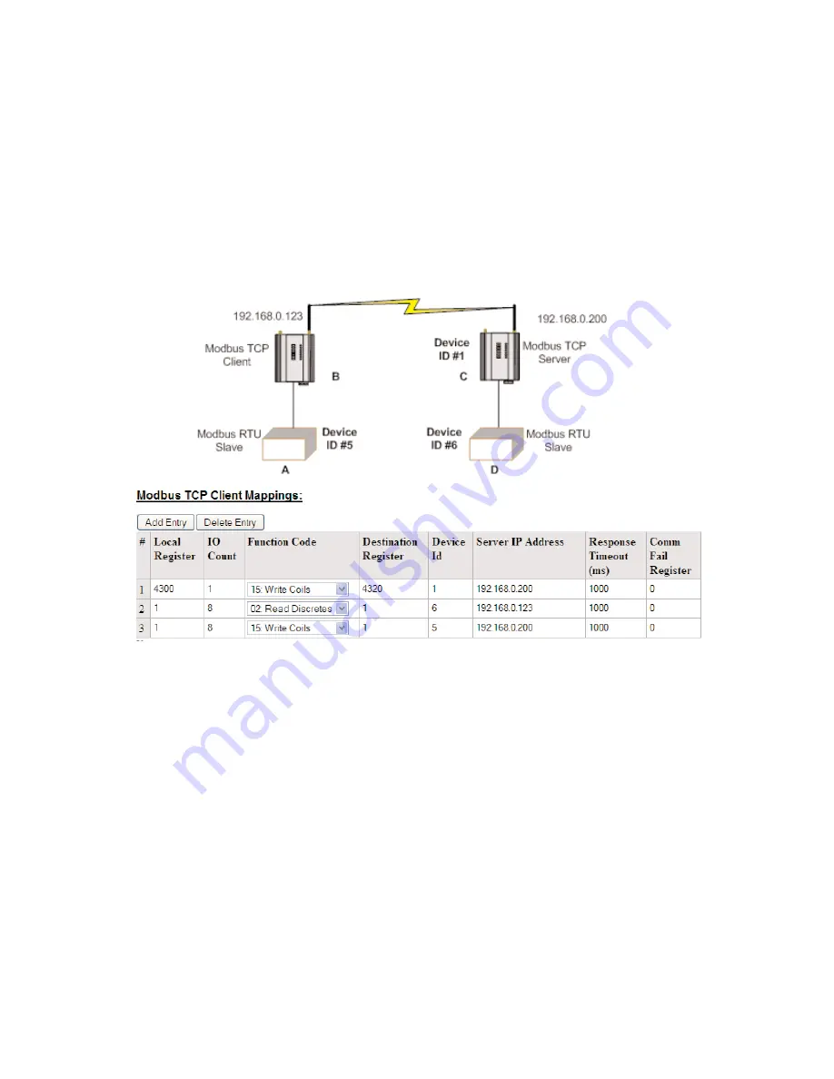
An example of the Modbus functionality of the BU-945U-E is illustrated below. In this example the status of the onboard digital input at C will be
reflected at the onboard digital output at B. Also, 8 single bit registers from Modbus serial device D will be transferred to A.
Unit B is configured with Modbus TCP Server enabled and Device ID = 1, Unit C is configured as shown above.
• The first will write the register 4300 (Local Digital Input) to server IP address 192.168.0.200 (Unit B), Device ID #1, register 4320
(Local Digital output).
• The second mapping shows a Modbus read command of 8 Discretes starting at register 1 (Destination Reg) on Device ID #6 connected to IP
address 192.168.0.123 (it self) and store the values at register #1 locally.
• The third mapping shows the Modbus write command (Write Coils) which is writing the local 8 I/O’s starting at register 1 across to Server IP
address 192.168.0.200, Device ID #5, destination reg #1.
The configuration of unit B is shown below (accessible via the “I/O Transfer” configuration page). It can be seen that Modbus TCP Client has been
enabled with a 500msec scan rate, meaning that there will be a 500msec delay between each of the mappings directed at any server. The “Reset
Registers on Comms Fail” option is enabled with a timeout of 60 seconds, indicating that any of the registers at unit B will be reset if a successful
Modbus transaction involving that register has not been executed in the last 60 seconds. The Modbus TCP to RTU Gateway at B must also be
enabled (see section “3.13.3 Modbus TCP to RTU Gateway”) to allow Modbus communications with the serial device A.