background image

Apricus Installation Manual 


12


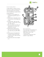
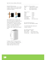
Expansion Vessel Connection Kit 

CoolSky also provide an expansion vessel 
connection kit to connect the expansion 
vessel to the safety group on the pumping 
station.  Each kit includes a wall fixing 
bracket and a self-closing system isolation 
valve (so that the vessel can be removed for 
maintenance without draining the fluid from 
the system and to facilitate periodic gas 
charge checks). 


A pre-formed stainless steel flexible hose is 
also provided to connect the vessel to the 
system at the connection point provided on 
the CoolSky Solar Pumping Station. 


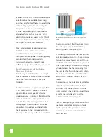
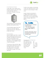
It is recommended that the Pumping Station 
and Expansion Vessel are located as far 
hydraulically away in the Solar Loop from the 
Solar Collector as is practically possible. This 
is to protect the Pumping Station and 
Expansion Vessel from the very high 

temperatures (i.e. >200 °C) that can be 
generated by a Vacuum Tube Collector 
under stagnation conditions. 
 

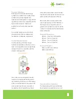
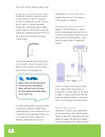
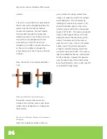
Mounting the Expansion Vessel


Always mount solar vessels in a vertical 
position and recognised best practice is to 
connect to the provided connection port on 
the pump station. Where possible, mount 
below the pump station to negate heat 
transfer. 


Avoid mounting in close proximity to the 
solar collector where temperatures can 
exceed 130°C. In cases where this cannot be 
avoided, it is highly recommended that the 
expansion vessel be installed in conjunction 
with a heat protecting ‘intermediate’ vessel. 


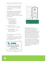
Intermediate Vessels 

Intermediate vessels are also available and 
are recommended on solar thermal systems 
where it is likely that temperatures within the 
system will exceed the maximum allowable 
working temperature of the expansion vessel 


Cool Tip


Always check the internal pressure 
of the Expansion Vessel before 
fitting and reset to 0.3 bar lower 
than the intended cold-fill pressure 
of the Solar Loop.   
 

Summary of Contents for Apricus

Page 1: ...CoolSky Ltd 42 Milecross Road Newtownards BT23 4SR Tel 44 0 28 9182 9470 Email info cool sky co uk Company Registration No NI072166 VAT No GB 108838970 Copyright 2012 CoolSky ...

Page 2: ... Loading 26 Back Up Heating Source 29 Anti Scald Tempering Valves 29 Closed Loop Max Incoming Pressure 29 Maximum Allowable Pressure 29 Electrical Supply 30 Labelling 30 Building Considerations 31 Health Safety Considerations 32 Installation Guidelines 34 Manifold and Bottom Support Track Assembly 35 Other System Components 37 Collector Installation 38 Connection to Plumbing 44 Insulation 44 Insta...

Page 3: ...packaging have been carefully designed so that they can be efficiently recycled at end of life Solar Energy Solar Energy is the planet s most abundant source of energy with the added benefit that it is both clean and free Source EU Commission Joint Research Centre Whilst the UK and Ireland are considered to have mild and temperate climates there are parts of the UK that can receive annual radiatio...

Page 4: ...he water to start boiling at temperatures as low as 30 C The water vapour generated when boiling rapidly rises to the top of the heat pipe where it condenses and transfers its thermal energy to the condenser and into the copper header pipe within the manifold Fig 2 Schematic showing the basic layout of a simple solar thermal system The condensed fluid then flows back down the heat pipe and is re h...

Page 5: ...orber tube is encased within a strong borosilicate glass enclosure that is then placed under ultra high vacuum conditions to ensure the ultimate performance in terms of thermal insulation A getter coating at the bottom of the tube is used to maintain the ultra high vacuum level within the tube throughout its operational lifetime and to ensure maximum collector efficiency is achieved Apricus tubes ...

Page 6: ... Max Pressure 8 bar Stagnation Temp 219 C Absorption 92 Emission 8 Width x Length 1496 x 2005 mm Height 156 mm Performance Figures η0 62 6 a1 1 595 a2 0 013 Model APRICUS APSE 30 Aperture Area 2 82 m2 Gross Area 4 35 m2 Weight Dry 95 kg Fluid Capacity 0 71 litres Max Pressure 8 bar Stagnation Temp 219 C Absorption 92 Emission 8 Width x Length 2196 x 2005 mm Height 156 mm Performance Figures η0 68 ...

Page 7: ... transfer heat from an independent heating source eg transferring heat from a central heating boiler or solid fuel boiler to the water in the solar cylinder and the solar coil which is manufactured from high efficiency finned tubes with a large surface area to transfer heat from the solar panels into the solar hot water cylinder with maximum efficiency We are also able to supply custom sizes upon ...

Page 8: ... be fitted with a PTRV All tanks should be supplied as standard with an approved valve Building Regulations The installation of unvented hot water cylinder for domestic applications is regulated under Building Regulation G3 for England and Wales Technical Standard P3 for Scotland Building Regulation P5 for Northern Ireland and Technical Guidance Document L for the Republic of Ireland All local rel...

Page 9: ...ns 1 BSP 130mm class TF110 VDE CE 4 Return side isolation valve DN20 with integrated bracket Connection M always open on one side 5 Integrated high temperature check valves Closure at 90 and opening at 45 Check valve opening 2kPa 200mm c a 6 Pressure gauge with integrated safety relief valve typ 6Bar with discharge connection point for isolation valve and expansion vessel 7 Air stop device with ma...

Page 10: ... ST 15 8 High Head Pump 8m head If multiple banks of collectors are installed in parallel the head loss should be calculated based on the longest pipe run through a single bank of collectors and then the pump can be sized to meet the total flow rate requirements Please Note that Drain back Systems will typically require a larger rated pump Flow Meter The CoolSky Pumping Staions include a flow mete...

Page 11: ...ermal solar systems The membrane is stable with the Pre Mixed Propylene Glycol within the solar loop up to 50 mixtures and has a max working temperature of 110 C The vessel can accommodate short peaks of 130 C glycol temperature The Zilan E solar membrane is also less likely to trap air and consequently there is a lower likelihood of corrosion damage to the steel vessel Expansion Vessels are manuf...

Page 12: ...om the very high temperatures i e 200 C that can be generated by a Vacuum Tube Collector under stagnation conditions Mounting the Expansion Vessel Always mount solar vessels in a vertical position and recognised best practice is to connect to the provided connection port on the pump station Where possible mount below the pump station to negate heat transfer Avoid mounting in close proximity to the...

Page 13: ...gnation periods the very hot solar fluid in the collectors can reach vaporisation point If this occurs the very hot solar fluid is forced out by the vapour into the expansion vessel Intermediate vessels have inlet outlet connections and are installed just before the main expansion vessel as shown above The heat sink that the intermediate vessel provides reduces the working temperature at the diaph...

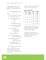
Page 14: ... PRV HST Static Height of System Height of Collector from Pump PEV Gas Pressure of Expansion Vessel 1 0 1 x HST CoolSky recommend that an additional safety factor of 1 5 is applied to the VEV value to account for the possibility of steam in the solar loop Examples of typical domestic Expansion Tank Capacities are given in the table below Apricus AP 30 Collector Aperture Area m2 System Volume Litre...

Page 15: ...ions Although some Solar Controllers are provided with a Frost Protect Function it must be highlighted that this only functions when there is electrical power provided to the controller and pumps In the UK and Ireland it is not unusual for extremely cold weather conditions to be accompanied by power outages due to falling power lines thereby rendering the Frost Protection Function ineffective Only...

Page 16: ...rts clubs The Apricus HD 25 is an ideal solution to protect from excessive overheating and can prevent premature ageing of the heat transfer fluids used in the solar loop Materials of Construction Piping Copper Ag Zn Cu brazed Fins 3A21 Grade Aluminium Case 3A21 Grade Aluminium Dimensions Height 500mm Depth 172mm Width 375mm Heat Transfer Area 2 8 m2 Gross Weight 6 6 kg Inlet Outlet Pipe Ø15 mm x ...

Page 17: ...ential damage to those areas surrounding the valve The unit is manufactured from high temperature grade plastic material that is suitable for solar systems and up to 160 C short bursts of glycol steam The captured fluid is visible through the opaque tank which is supplied complete with a drain valve Technical Specification Capacity 9 6 litre Drain valve integral Size 300 x 270 x 130mm Clearance re...

Page 18: ...l Design Team can also offer our customers a full bespoke design service System designs and configurations for both small and large systems can be tailored to our customers particular requirements Contact CoolSky for more details on our Free Design Service Collector Direction Ideally the collector should face as close to due South as possible A deviation of up to 15o to the East or West is accepta...

Page 19: ...g multiple rows of collectors consider the shading of collectors on the row behind especially in the winter Location of Collector The collector should be positioned as close as possible to the storage tank to avoid long pipe runs System Sizing Domestic System Sizing For residential domestic water heating applications basic rules of thumb exist that allow system sizes to be calculated using the met...

Page 20: ...mand for Domestic Hot Water Commercial Collector Sizing Sizing a commercial system usually requires the use of professional modelling software CoolSky can offer a free design service to our customers for these jobs The table below gives guidelines to typical Hot Water Demands in commercial applications Type of Building Max Liters of Hot Water at 60 C per person Restaurant 6 Factory 15 Offices 14 H...

Page 21: ...uency and duration for the sake of overall system efficiency Otherwise the longevity of the evacuated tubes may be compromised by more rapidly reducing the vacuum level Commercial Cylinder Sizing Sizing storage for commercial applications is more complex than residential sizing and requires a detailed evaluation of hot water usage patterns Commercial applications are too varied in demand peak dema...

Page 22: ...DN20 90 240 25mm DN25 Guidelines showing pipe sizing for typical domestic installations Securing Pipes Pipes must be secured in place with suitable brackets straps etc according to plumbing code requirements for material and pipe diameter and to prevent vibration and placing stress on system components Internal Piping Extra care must be taken to avoid any piping leaks inside the building Avoid joi...

Page 23: ...ing The system should be sized so that overheating of the tank is difficult to achieve in a single day even during hot sunny periods For properly sized open and closed loop systems with suitable heat transfer fluid it is acceptable for the system design to allow the solar collector to stagnate i e stop the pump from time to time to prevent overheating of the storage tank above the maximum cylinder...

Page 24: ...r underground thermal store Increased Angle Reduces Summer Output Apart from installing a smaller collector a good method of reducing summer heat output is to angle the collector for optimal winter absorption This is achieved by installing the collector at an angle 15 20 above the latitude angle so long as the collector remains within the recommended angles of 20 to 80 This angle corresponds close...

Page 25: ...be collectors in series in parallel the flow rate through each bank MUST be equal Otherwise some collectors will run cold due to higher flow rate while others will run hot due to lack of flow This is not an issue for a single bank of up to 150 tubes connected in series Reverse Return plumbing or first in last out is an effective piping configuration that helps to ensure balanced flow However there...

Page 26: ...both rear and frontal winds The highest force of 180 kg on the middle front foot at a 60 collector angle is actually from a frontal and not rear wind as it is trying to tip the collector backward Based on the figures provided in Table A the weight of individual concrete blocks or the strength of fixation points requirements can be determined NOTE A safety factor of at least 1 2 should be used or a...

Page 27: ...led at an angle of 50o or greater to promote snow sliding off the tubes In addition it is advisable to raise the front of the collector frame 15 to 20cm off the roof surface as this allows the collector to sit above moderate snow falls and allow snow to blow away from under the collector A front track extension available from CoolSky can be used for this purpose Each tube is strong enough to withs...

Page 28: ...ing of basins baths etc Ultraviolet UV degradation Any components installed outside must be able to withstand UV radiation without significant degradation Colour fading is common but cracking peeling and other severe degradation should not occur during the design life of any component in the system Coastal Regions Apricus collectors are manufactured using 439 301 and 304 grade stainless steels for...

Page 29: ...m being overheated Hot water storage cylinders should comply with the local building regulations and be fitted with the appropriate safety features for over temperature and over pressure protection Anti Scald Tempering Valves Anit scald mechanisms are required in order to comply with the MCS MIS3001 Section 4 3 3 Requirement Incorporate a means to limit the water at all points of use to no more th...

Page 30: ...s and pressures of the system design System pressures that exceed those requirements outlined above will void the warranty Electrical Supply Any electrical work must be completed by a licensed electrician and or in accordance with relevant electrical codes and building regulations Power supply to the controller must be protected again water ingress Power supply to the controller must be disconnect...

Page 31: ...st be sealed to prevent water vermin or any other intrusion Structural Supports Any points of attachment for the solar collector or other system components must be of suitable structural strength to support the weight of the components plus any loads that may be encountered such as wind or snow loading Any damage to structural supports caused by screws drilled holes or other fastening methods must...

Page 32: ...ace for the organisation and performance of work at height Safe systems and methods are in place for selecting equipment that is suitable to undertake the work Safe systems and methods are in place for protecting people from the consequences of working at height The Regulations set out a basic hierarchy for managing and selecting equipment for work at height as follows Avoid working at height wher...

Page 33: ... on site risks such as slippery roofs exposed nails hot plumbing sunburn high winds etc Safety on the roof is always an important consideration Avoid roof work if it is raining and ensure that the inside of the manifold does not get wet Do not let rain enter the evacuated tubes Keep the evacuated tubes out of the sun until 2 3 minutes prior to installation If you install the solar collector in dir...

Page 34: ...bes from Sunlight Do not expose the tubes to sunlight until ready to install otherwise the heat pipe tip will become very hot and can cause serious skin burns The outer glass surface should not become hot Frame Manifold Unpack Inspect Unpack the standard frame that is provided together with the manifold Apricus solar collectors are come with a standard frame which is suitable for flush mounting on...

Page 35: ...ricus offers rubber pads which are perfect for separating the metals see image below Fasteners It is recommended that stainless steel fasteners are used If using galvanized steel bolts separate dissimilar metals using a nylon or high density EPDM Silicone rubber washer Manifold and Bottom Support Track Assembly The Manifold and Bottom Track are secured to the standard frame channels using special ...

Page 36: ... threads and helps prevent you from loosening the bolt so much that the nut drops off The bolt head is prevented from rotating by use of nut locks i e rectangular washers removing the need to use a second wrench underneath the frame and aiding a quick and easy assembly process Customizing the Frame The standard frame together with the adjustable angle frame kit components can be adapted to a wide ...

Page 37: ...eze based Heat transfer fluid Flush Fill Pumping Cart Anti scald valve Various plumbing fittings valves drain valves etc Scissor lift cherry picker and or ladders and harness equipment for roof work Labels and permanent marker to label system components and flow paths Cool Tip All system components should be installed in a manner that allows access for maintenance and repairs Support Rail Side Rai...

Page 38: ...ent point Ensure that any additions or modifications to the roof structure meet structural requirement and local building regulations A Horizontal Brace is provided with the standard frame kit This gives a useful indication of the typical spacing between frame side rails Additional holes may be drilled in the horizontal brace to meet different roofing rafter locations The Horizontal Brace componen...

Page 39: ...rectly aligned The manifold and bottom track will lock into the frame secured from above and below with the attachment plates that are already in place Make sure that the Manifold and Bottom Support Rail are square with the frame side rails To ensure proper tube engagement each tube in the Manifold should line up with the corresponding cradle on the Bottom Support Rail Each Tube is installed with ...

Page 40: ...f Metal Roof Kit For installations where longer bolts may be required to account for the height of the ridges such that the required depth of penetration into the rafter is achieved or there is a desire to hold the collector frame away from the roof structure the Stand Off Metal Roof Kit is suitable Each kit consists of 4 or 6 large hanger bolts M10 x 250mm with integral rubber seals attachment pl...

Page 41: ... the ground on a clear flat area The collector frames are relatively light and can easily be carried onto the roof once assembled Assembling on the roof is both dangerous and makes it easy to lose bolts and nuts that may roll away Frame Feet Anchoring Frame feet should be bolted to the installation surface using 8 mm diameter stainless steel bolts or a similarly sturdy fastening method Galvanized ...

Page 42: ...r feet may be raised Raising the angle greatly increases the horizontal force during high winds and may require additional structural and or hardware upgrades Consult a building engineer for design requirements Standard Frame Support Rail Standard Frame Side Rail Diagonal Brace Top Rear Leg Bottom Rear Leg When fitting place the large metal washers between the inner wall of the side rail and the o...

Page 43: ...uctural integrity of the wall If the wall construction is not suitable for the load it will be necessary to reinforce the wall frame accordingly Consult a building engineer for design requirements Recommended Angle Ideally do not install the collector beyond an angle of 80o close to vertical otherwise heat pipe operation will be impaired by 10 or greater Installing vertically is permitted and will...

Page 44: ...or tarpaulin to the glass tubes as this can result in damage breakage of the glass under high wind conditions Damage to collectors and other components incurred by extended dry or wet stagnation is not eligible for warranty claims Pipework Suitable Pipe Materials Only the following materials are recommended for use with High Performance Evacuated Tube Solar Collector Systems as follows Flexible St...

Page 45: ...oam a high quality silicone sealant should be used to form a water tight seal This is also important to avoid water running down under the insulation along the copper stainless steel pipe into the roof space Protect Insulation EPDM foam insulation that is exposed to direct sunlight should be protected against UV related degradation CoolSky supply Stainless Steel Flexible Pipework that is pre insul...

Page 46: ...eds to be before installing the tube and heat pipe they should inverted condenser end down returned upright condenser at top and then shaken up and down a few times to ensure the powder has all returned to the bottom This should be done at ground level Damaged Tube If an evacuated tube is damaged for any reason E g knocked heavily or dropped it will need to be replaced Never throw heat pipes away ...

Page 47: ...d remove any excess from the tip Using this method half a tube can coat 30 tubes Heat Pipe and Evacuated Tube Insertion Lubricate the top outer surface of the evacuated tube with a small amount of water This facilitates easy insertion past the manifold rubber ring seal A small pump spray bottle is the best method for carrying and applying the water NOTE DO NOT SPRAY WATER INTO THE EVACUATED TUBE C...

Page 48: ... pipe will be turned out of alignment with the top of the tube which will prevent proper heat pipe operation Correct Insertion Depth The heat pipe and evacuated tube are fully inserted once the black coating of the evacuated tube has disappeared up into the manifold and no clear glass above the coating is visible Securing the Tube Position the rubber end cap so it is aligned with the corresponding...

Page 49: ...the clip with the hook on the bottom support rail and push down over the rubber cap Removal of the Securing Clip The clip can be removed by using a screwdriver or needle nosed pliers to pull each side of the clip down and outward Very little force is required Post Installation Cleaning Clean each evacuated tube with a fluid glass cleaner and cloth then dry clean with newspaper ...

Page 50: ...o allow for further air bleeding of the solar loop if required Commissioning Method Connect the Flow Hose from the Flush and Fill Cart to the Filling Valve 1 and open the valve Connect the Return Hose to the Drain Valve 2 and open the valve Close the Restrictor Flow Valve 3 so that the slot is in a horizontal position Open the Cold Check Valve 4 by turning so that the 45 indicator is facing upward...

Page 51: ...ff Monitor the system pressure gauge for any drop in pressure that may indicate a leak in the pipework Open the Restrictor Flow Valve 3 so that the slot is in a vertical position Close the Cold Check Valve 4 by turning so that the 90 indicator is facing upwards i e the gauge is now in the correct orientation Close the Hot Check Valve 5 by turning so that the 90 indicator is facing upwards i e the ...

Page 52: ... is fully commissioned the solar collector will begin to produce heat after a 5 10 minute warm up period when the sun is shining Check the controller and pump for correct operation and adjust settings as required Make sure that you have changed the controller setting from ON to AUTOMATIC Clean Up Once the system is confirmed as operating correctly ensure the installation site is cleaned of all rub...

Page 53: ...ptimum system operation The following maintenance may ONLY be completed by AUTHORIZED PERSONS Broken Tube If a tube breaks it should be replaced as soon as possible Whilst the system will still operate normally and safely with a broken tube it will be at a slightly reduced level of performance To ensure maximum collector performance any broken tubes should be replaced Always wear safety goggles an...

Page 54: ...ere has been a drop loss of pressure in the solar loop it will need to be recharged re pressurised The solar system should only be topped up with the SAME glycol fluid as was used to originally fill the solar loop Water must NEVER be used to top up the system as this can result in the dilution of the anti freeze protection and leave the system susceptible to freezing Draining the Collector During ...

Page 55: ... minimum the following maintenance schedule is followed Other Components Other parts of the system such as the storage tank and the back up heating boiler should be serviced and inspected according to their specific manufacturer s maintenance guidelines ...

Page 56: ...collector location for possible shading Excessive System Flow Rate Reduce flow rate by adjusting restrictor screw on the flow meter Reduce the Pump Speed Select Slower Speed Controller Settings Incorrect Check if differential dT function is correct dTMin may be set too high Trying reducing to 2 C Pump is always ON even during minimal solar radiation Insufficient Flow Rate Check flow gauge for prop...

Page 57: ... issue the ensure installation angle is increased to least 45 Heat Loss from Pipes Check that insulation is still in good condition with no exposed hot pipes Damage to Evacuated Tubes Check that evacuated tubes are all intact and that the getter at the bottom of the tubes remains silver coloured Heat Pipes Not Operating Check that heat pipes are making good contact in the manifold header and are h...

Page 58: ...gh Hot Water Back Up Heating Is back up heating system functioning normally Faulty Temperature Mixing Valve Check operation of Temperature Mixing Valves Increased Hot Water Demand Has demand in the property for hot water increased May need installation of larger capacity boiler Boost settings on controllers may need revised Larger storage tank collector array may be required Intermittent short bur...

Page 59: ... may need purged using Flush Fill cart to remove entrapped air Fluid Dumping from the Pressure Relief Valve on the Pumping Station System Over Pressurised during installation Confirm cold fill pressure in Bar is in agreement with guideline of 1 3 0 1 x Static Height where static height is in Meters If over pressurised release some fluid pressure only under cold conditions Faulty Expansion Tank Rep...

Page 60: ...on of flammable materials Such cleaning may only be completed by the homeowner if the tubes are easily and safely accessible Inspection If there is any problem with the system the installer will generally ask the homeowner to inspect various portions of the system before making a service call The following inspections may be performed by the homeowner ONLY if they are easily and safely accessible ...

Page 61: ...dispose of in accordance with local regulations Once the collector is fully drained the pipe work can be disconnected from the system and the collector can be dismantled and the components set aside for recycling End of Life Recycling Once the Apricus Solar Collector has reached the end of its usable life it can be efficiently recycled Below are the main materials used in the solar collector all o...

Page 62: ...tee of any kind CoolSky Ltd disclaims all warranties and conditions with regard to this information including all implied warranties and conditions of merchantability fitness for a particular purpose title and non infringement In no event shall CoolSky Ltd or any subsidiaries or any suppliers be liable for any special indirect or consequential damages or any damages whatsoever resulting from loss ...

Page 63: ...on the other side Because air can be compressed the expansion tank can accept the increase in fluid volume that results when the temperature of the system increases This prevents dumping of fluid from the pressure relief valve Solar Flow Line The plumbing line supplying heated fluid FROM the Collector TO the Storage Cylinder or heat exchanger Solar Return Line The plumbing line supplying heated fl...

Page 64: ...er 2 minutes at 60 C or after 2 hours at 50 C BACTERIA IN SOLAR SYSTEMS Solar irradiation during the winter periods in the UK and Ireland may only contribute to approximately 10 20 of the hot water demand by pre heating the incoming cold water feed by way of example to temperatures of 20 C to 30 C This lower energy contribution from the solar collector can still reduce fossil fuel consumption duri...

Page 65: ...ntre etc then contact CoolSky Technical Support Office for guidance and advice on correct design solutions REFERENCE DOCUMENTS The installer should make himself familiar with the requirements of the following applicable documents and any other local or national regulations and guidelines in relation to legionella in hot water systems Issuing Body Document Health Safety Executive UK Code of Practic...

Page 66: ...Periods for Products supplied by CoolSky Ltd is limited to the benefit of any such warranty that is provided to CoolSky Ltd by the manufacturer of the Products Where the Manufacturer Warranty differs from that stated herein the Manufacturer warranty takes precedence Component Warranty Period Effective Date Solar Collector Copper Heat Transfer Header 15 Years Installation Date Solar Collector Mount...

Page 67: ... if unknown or unable to be contacted b Contact CoolSky Ltd directly CoolSky Ltd 42 Milecross Road Newtownards BT23 4SR Northern Ireland U K Email info cool sky co uk Tel 44 0 28 9182 9470 The following information may be required to determine if the Product issue is eligible for coverage under the terms of this Limited Warranty a Information related to the manner in which the Products were instal...

Page 68: ...n Ireland U K Tel 028 9182 9470 Email info cool sky co uk Web www cool sky co uk Copyright 2012 CoolSky Ltd CoolSky Ltd are Distributors for Apricus Solar Ltd Products in the UK and Ireland Apricus Solar Ltd are a global supplier of Solar Thermal Collectors and associated components P00538A ...

Reviews: