36
OPERATION CONTINUED
INTELLISTAT TS
TM
MONITOR OPERATION
ON MANUAL BYPASS
TIME: 07:58:17 AM
DATE: 03/31/10
X1
X2
LOW
BATTERY
CHARGE
LOAD %
MANUAL BYPASS
STATIC BYPASS
BATTERY
STATUS
INPUT
OUTPUT
PFC
LINK INVERTER
PARAM
ALARMS
SETUP
TEST
ON/OFF
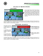
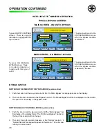
MAIN SCREEN - ON MANUAL BYPASS
ON STATIC BYPASS
TIME: 07:58:17 AM
DATE: 03/31/10
X1
X2
LOW
BATTERY
CHARGE
LOAD %
MANUAL BYPASS
STATIC BYPASS
BATTERY
STATUS
INPUT
OUTPUT
PFC
LINK INVERTER
PARAM
ALARMS
SETUP
TEST
ON/OFF
MAIN SCREEN - ON STATIC BYPASS
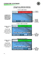
Typical ON MANUAL
BYPASS screen. There
is no alarm indication or
logging with this type of
event.
TYPICAL BYPASS SCREENS
Typical ON STATIC BYPASS
screen. There is no alarm
indication or logging with this
type of event.
The screen will return to the
SYSTEM NORMAL screen
when the bypass condition
is cleared by the user.
The screen will return to the
SYSTEM NORMAL screen
when the bypass condition
is corrected.
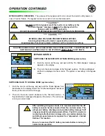
BYPASS SWITCH
SWITCHING THE INVERTER TO BYPASS MODE (system active).
1. Push the knob in all the way and wait until the “On Static Bypass” message appears on the display.
2. Then turn the knob clockwise to the “Bypass” position. “On Manual Bypass” will then be displayed on the monitor.
The system is now safely in the bypass mode.
SWITCHING BACK TO NORMAL MODE (system active).
1. Push the knob in all the way and wait until the “Static Bypass” bar
illuminates on the display (Note: The “On Manual Bypass” banner at
the top of the screen will not change).
2. Then turn the knob counter clockwise to the “Normal” position. A
“System Normal” message will appear on the screen. The unit is now
running in normal mode.
ON MANUAL BYPASS
TIME: 07:58:17 AM
DATE: 03/31/10
X1
X2
LOW
BATTERY
CHARGE
LOAD %
MANUAL BYPASS
STATIC BYPASS
BATTERY
STATUS
INPUT
OUTPUT
PFC
LINK
INVERTER
PARAM
ALARMS
SETUP
TEST
ON/OFF
Summary of Contents for MODEL ES
Page 51: ...51 APPENDIX A RELATIVE DRAWINGS SCHEMATICS APPENDIX A ...
Page 57: ...57 NOTES ...

