Control Techniques SM-Encoder Plus User Manual Download Page 34

34

SM-Encoder Plus User Guide

www.controltechniques.com

Issue Number:  3

SLX.HF

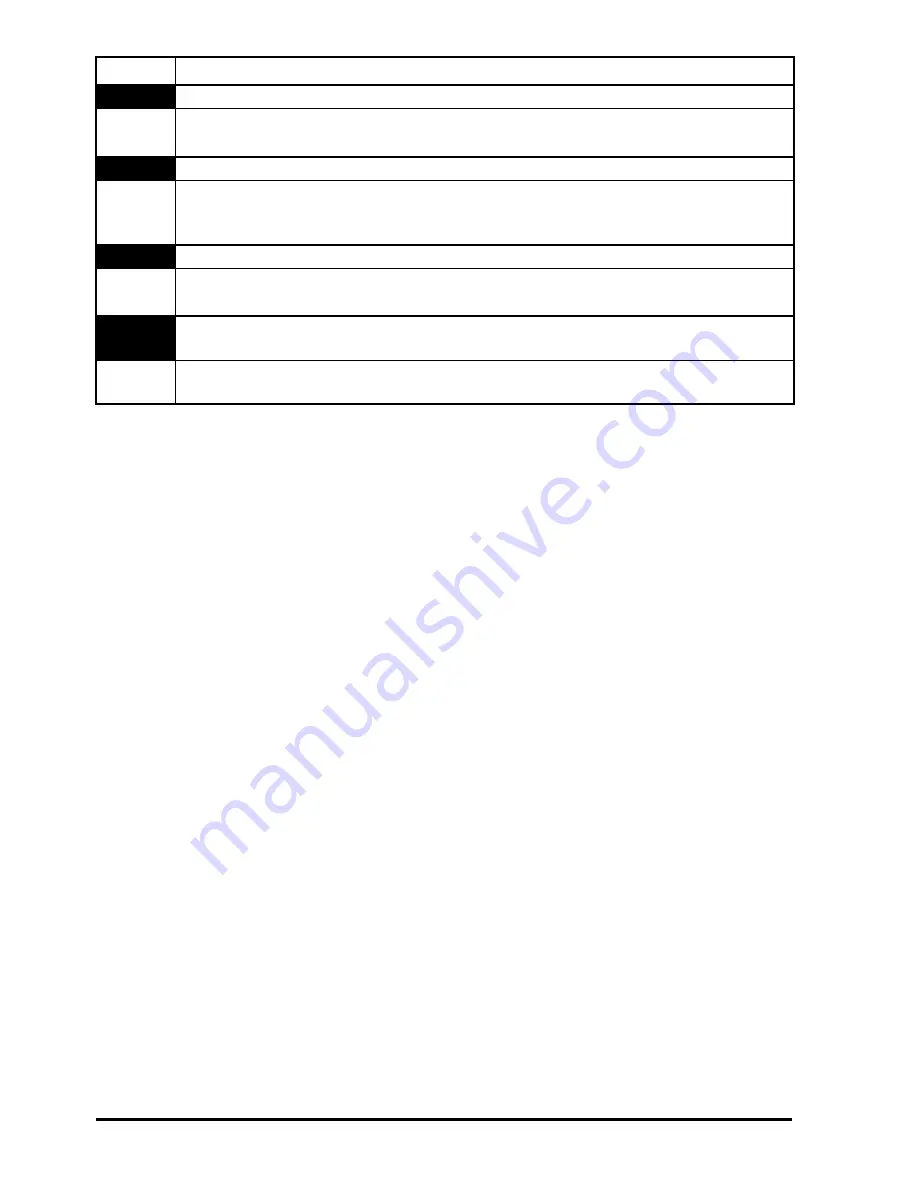
Solutions Module slot X trip: Solutions Module X hardware fault 

200,205,

210

Ensure Solutions Module is fitted correctly
Return Solutions Module to supplier

SLX.nF

Solutions Module slot X trip: Solutions Module has been removed 

203,208,

213

Ensure Solutions Module is fitted correctly
Replace Solutions Module
Save parameters and reset drive

SLX.tO

Solutions Module slot X trip: Solutions Module watchdog time-out 

203,208,

211

Press reset.
If the trip persists, contact the supplier of the drive.

SL.rtd

Solutions Module trip: Drive mode has changed and Solutions Module 
parameter routing is now incorrect 

215

Press reset.
If the trip persists, contact the supplier of the drive.

Trip

Diagnosis

Summary of Contents for SM-Encoder Plus

Page 1: ...EF www controltechniques com User Guide SM Encoder Plus Solutions Module for Unidrive SP Part Number 0471 0026 03 Issue Number 3...

Page 2: ...us development and improvement the manufacturer reserves the right to change the specification of the product or its performance or the contents of this guide without notice All rights reserved No par...

Page 3: ...eters 6 3 Introduction 7 3 1 Features 7 3 2 Solutions Module identification 7 3 3 Set up parameters 8 3 4 Compatible with encoder types 8 4 Installing the SM Encoder Plus 10 4 1 Solutions Module slots...

Page 4: ...ning and experience in system design installation commissioning and maintenance 1 2 Information This guide contains information covering the identification of the Solutions Module terminal layout for...

Page 5: ...er Guide carefully The STOP and SECURE DISABLE functions of the drive do not isolate dangerous voltages from the output of the drive or from any external option unit The supply must be disconnected by...

Page 6: ...r achieving compliance with specific EMC standards Within the European Union all machinery in which this product is used must comply with the following directives 98 37 EC Safety of machinery 89 336 E...

Page 7: ...identified by 1 The label located on the underside of the Solutions Module 2 The colour coding across the front of the Solutions Module All Unidrive SP Solutions Modules are colour coded with the SM E...

Page 8: ...e with a marker pulse which identifies each individual rotation of the disc and is also used to reset the drive position parameter The incremental encoder can be used when operating in Closed Loop Vec...

Page 9: ...al signals 360 electrical encoder 90 separation of A and B A A B B Z Z Marker signals Index alignment reference min max Only encoders with lines per revolution that are a power of 2 can be used with t...

Page 10: ...drive for at least 10 minutes 2 Ensure that both the 24V and 48V backup power supplies are disconnected from the drive for at least 10 minutes if used 3 Check that the exterior of the SM Encoder Plus...

Page 11: ...ule 8 Connect the AC supply to the drive 9 Set Pr 0 49 to L2 to unlock read only security 10 Check that Menu 15 slot 1 16 slot 2 or 17 slot 3 parameters are now available 11 Check that Pr 15 01 Pr 16...

Page 12: ...n to managing the cable shields Encoder mounting methods There are three methods for mounting an encoder onto a motor 1 Galvanic isolation between encoder and motor 2 Galvanic isolation between encode...

Page 13: ...h safety measures or to reduce radiated radio frequency emissions from either the drive or encoder 4 4 2 Encoder circuit with galvanic isolation from encoder body In this case the encoder device is mo...

Page 14: ...the data against this noise current but much more care is needed in ensuring correct cable management than for the isolated cases Figure 4 7 No isolation Motor Shaft Motor Housing Encoder Housing No...

Page 15: ...and to maximise the shielding benefit Cable shield ground connection For all mounting methods grounding of the feedback cable shield has added benefits It can protect the drive and encoder from induce...

Page 16: ...ections Ensure that feedback cables are kept as far away as possible from power cables and avoid parallel routing NOTE Cable Cable shield Twisted pair shield Cable shield Twisted pair shield Connectio...

Page 17: ...e and that the encoder feedback wiring and shielding recommendations are followed in section 4 4 Wiring Shield connections on page 12 The control circuits are isolated from the power circuits in the d...

Page 18: ...2 or 3 the error detection for the drive encoder is disabled Pr 3 40 0 when no drive encoder is connected Slot identification Identify which Solutions Module slot and menu are being used Slot 1 Menu 1...

Page 19: ...bined update time depends on the number and type of dumb modules fitted to the drive For each dumb module the update rate of these parameters is specified as either 4 or 8ms The combined update time i...

Page 20: ...the drive keypad for easy viewing DE Destination indicates that this parameter can be a destination parameter RA Rating dependant this parameter is likely to have different values and ranges with driv...

Page 21: ...pe Ab 0 Fd 1 Fr 2 Ab 0 RW Uni US x 16 Encoder termination 0 to 2 1 RW Bit US x 17 No function x 18 No function x 19 Feedback filter 0 to 5 0 to 16 ms 0 RW Uni US x 20 No function x 21 No function x 22...

Page 22: ...RW Bit x 50 Solutions Module error status 0 to 255 RO Uni NC PT x 51 No function Parameter Range Default Type OL CL OL VT SV RW Read Write RO Read only Uni Unipolar Bi Bi polar Bit Bit parameter Txt...

Page 23: ...SM Encoder Plus User Guide 23 Issue Number 3 www controltechniques com...

Page 24: ...32 x 33 Position Revolution counter Marker position information x 45 Position feedback initialised x 07 Marker position disable x 16 Encoder termination x 15 Encoder type Marker flag _ SM Application...

Page 25: ...x 03 x 19 Feedback filter Speed 0 XX 0 XX Key Read write RW parameter Read only RO parameter Input terminals Output terminals The parameters are all shown at their default settings x 04 x 05 Position...

Page 26: ...nt Solutions Module fitted or no Solutions Module fitted where one was previously fitted the drive gives a Slot dF or SLot nf trip The SM Encoder Plus is a dumb module and contains no software This pa...

Page 27: ...elected the resolver produces 4 096 counts per revolution and so the position is represented by the bits in the shaded area only When the feedback device rotates by more than one revolution the revolu...

Page 28: ...10 can be set to any value from 0 to 50 000 there are restrictions on the values actually used as follows If Pr x 10 2 ELPR 2 If Pr x 10 16 384 ELPR 16 384 Otherwise Pr x 10 is rounded down to the nea...

Page 29: ...ive if the parameter value is 0 or 1ms but operates over the defined window for parameter values of 2 4 8 and 16ms Pr x 29 and Pr x 30 are duplicates of Pr x 04 and Pr x 05 respectively and not affect...

Page 30: ...st be reset by the user before the next freeze event is stored At power up Pr x 45 is initially OFF 0 but is set to On 1 when the SM Encoder Plus x 32 Marker revolution counter RO Uni NC PT 0 to 65 53...

Page 31: ...ber A value of zero indicates the Solutions Module has not detected an error a non zero value indicates that an error has been detected See Table 7 1 Trip codes on page 33 for the meaning of the value...

Page 32: ...trip in Pr 10 43 to Pr 10 51 The time of the trip is recorded from the powered up clock if Pr 6 28 0 or from the run time clock if Pr 6 28 1 Pr 10 20 is the most recent trip or the current trip if the...

Page 33: ...digital outputs plus the SM I O Plus digital outputs or the drive s main encoder supply plus the SM Universal Encoder Plus encoder supply Reduce load and reset Provide an external 24V 50W power supply...

Page 34: ...odule has been removed 203 208 213 Ensure Solutions Module is fitted correctly Replace Solutions Module Save parameters and reset drive SLX tO Solutions Module slot X trip Solutions Module watchdog ti...

Page 35: ...rection or Reverse inputs 5 Marker pulse channel Z 6 Marker pulse channel Z Type EIA 485 differential receivers Maximum frequency 600kHz Line loading 2 unit loads for terminals 1 to 4 32 unit loads fo...

Page 36: ...Encoder type 28 Encoder with galvanic isolation from motor 13 Environmental limits 6 F Features 7 Feedback cable 15 17 Feedback cable connections 16 Feedback filter 29 Freeze data 30 Freeze function 1...

Page 37: ...arameter structure 19 Parameters adjusting 6 Power cables 16 Power supply overload 33 S Safety of personnel 5 SECURE DISABLE 5 Set up parameters 8 Shield connections 12 15 Solutions Module ID code 26...

Page 38: ...0471 0026 03...

Reviews: