background image

Quick Start Guide

Quick Start Guide - Ultra JR50 Ethernet Data Radio 

11

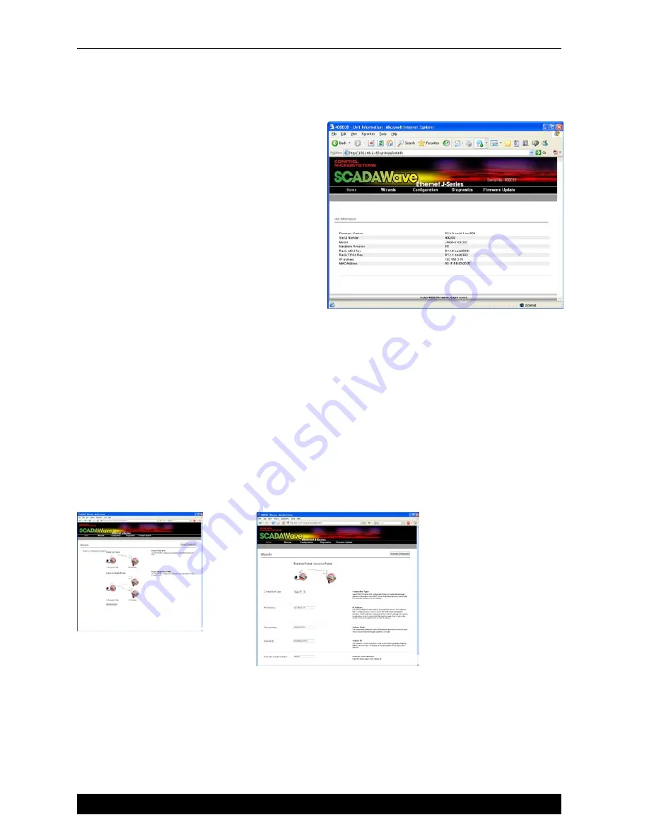
Step 4 - Start Web Browser on your PC

Start your web browser and insert the IP 
address of the J Series into the URL. In 
this case, we type “192.168.2.15” and the 
configuration page is now displayed in the 
browser.
Click on the “Wizards” button to activate the 
Wizards menu in the HTML configuration 
programmer.  

Step 5 - Activate Access Point - 

PTP Wizard

Select Point to Point - Access Point

Select the “Point to Point - Access Point” button 
and click on the “Start The Wizard” button. The Access Point Wizard screen is now shown. 
The Wizard now prompts the user to configure some critical items for point to point operation.  
For each configuration item, help text is provided on the HTML programmer interface.  If you are 
manually specifying IP addresses, ensure you record them for future reference. You will need to 
know the IP address of each radio in future steps. 
Note: The SubNet ID  should be a descriptive text name for the radio link. It MUST be identical 
in both Access Point and Remote radios for correct operation to occur.  You can not save the 
configuration with the factory default SubNet ID.  Choose a unique ID and make sure it is 
recorded.Up to 20 printable characters can be used.
After configuration of all items are complete, activate the configuration by clicking on the 
“Activate Configuration” button in the top right corner. 
Click on the “Write” button to send this configuration to the radio

Summary of Contents for SCADAWave Ultra JR5O

Page 1: ...Quick Start Guide for the Ultra JR50 Ethernet Data Radio This guide provides step by step instructions with simple explanations to get you up and running For further information please refer to the S...

Page 2: ...rating Voltage 10 30 Volts DC Power Supply Protection and Precautions The J Series Radio is supplied with the a mating DC power connector Phoenix Contact Part Number 1777989 The DC Power connector sho...

Page 3: ...cable should be used for installation to comply with ETSI EMC directives Serial Port A B Ports The J Series Radio features a 9 pin miniature D Shell DE 9 Female connector that supports two individual...

Page 4: ...na for Rx Signal When using a directional antenna it will be necessary to align the antenna for the best received signal This can be done using TVIEW Diagnostics or by measuring the RSSI output on Pin...

Page 5: ...g RED LED indicates the REMOTE is not synchronised to a Access Point or BRIDGE Check the antenna all RF connections and the radio configuration as the Subnet ID may not match the Access Point or there...

Page 6: ...IP address of the J Series It is strongly recommended that you follow these guidelines for successful connection to the radio 1 Ensure the J Series is powered up and has fully booted This is indicated...

Page 7: ...k Administrator before allocating IP addresses as each LAN WAN network is different 5 You should start your web browser and insert the IP address of the J Series into the URL In this case we type 192...

Page 8: ...window Checking IP connectivity The most reliable way to check IP connectivity to a device is using the Ping utility Type ping xxx where xxx is the complete IP address of the destination device you wa...

Page 9: ...n It is recommended that whip antennas are not used to simulate a long distance RF link RF attenuators are far superior to antennas for short distance bench testing as the attenuation of the RF signal...

Page 10: ...the radio you will need to reset the radio configuration to factory default This can be done by powering up the radio wait 45 seconds depress the factory default switch using a paper clip or similar t...

Page 11: ...some critical items for point to point operation For each configuration item help text is provided on the HTML programmer interface If you are manually specifying IP addresses ensure you record them f...

Page 12: ...Point Step 8 Embedded Diagnostics Testing 8 1 Review Access Point Start your web browser and insert the IP address of the J Series Access Point as recorded in Step 6 into the URL Once loaded click on...

Page 13: ...cord After an Indicative Packet Error test has been performed a Commissioning Record can be prepared This facility is activated by clicking on the Commissioning Record button It is recommended that th...

Page 14: ...ass I Division 2 wiring in accordance with the electrical codes The enclosure and wiring are subject to investigation by the local Authority Having Jurisdiction at the time of installation 3 Installat...

Page 15: ...ce operations at closer than this distance is not recommended The antenna used for this transmitter must not be co located in conjunction with any other antenna or transmitter MAXIMUM EIRP FCCRegulati...

Page 16: ...ROL MICROSYSTEMS www controlmicrosystems com Ottawa n Calgary n Denver n Houston n Melbourne n Leiden Within North America 888 267 2232 n Outside North America 613 591 1943 Control Microsystems reserv...

Reviews: