6
Relay properties
•
Relay 1 Power Up State
and
Relay 2 Power Up State:
(Read
only) Represents the status of the relays if IO Option
1
,
3
,
4
, or
5
is selected. The options are
Restore Last State
,
Set To OPEN
,
and
Set To CLOSED
. The default is
Restore Last State
.
•
Relay 1 Status
and
Relay 2 Status:
(Read only) Represents the
status of the relays if IO Option
1
,
3
,
4
, or
5
is selected.
Actions tab
Buttons located on the
Actions
tab allow you to view version and
diagnostic information and force relay actions. (Relay actions will
always be shown, regardless of the IO configuration.)
•
Version Information:
This action button will display the versions
of the driver’s Base Template and Template, as well as the
Boot Loader to the
Lua Output
window of the
Lua
tab. The
Log
Mode
property does not have to be set to Print to display this
information to the window.
•
Diagnostic Information:
This action button will display the
following information to the
Lua Output
window of the
Lua
tab (the
Log Mode
property does not have to be set to Print to
display this information to the window): device Zigbee MAC
address, Zigbee mesh PAN id, Template Version, Base Template
Version, Boot Loader Version, Zigbee Node ID.
•
Relay 1 Close
and
Relay 2 Close:
These action buttons will
trigger the corresponding relay to close.
•
Relay 1 Open
and
Relay 2 Open:
These action buttons will
trigger the corresponding relay to open.
Troubleshooting
If the device is not working:
• Reboot the device by disconnecting power, then re-connecting
power.
• Check for proper wiring. See the “Wiring Configuration” diagrams.
• Review the log in the driver’s Lua tab.
• Restore factory defaults (13 button presses).
Note:
Un-identifying a device off the Zigbee mesh will cause it to do a
factory reset. A factory reset reverts all relays to the open state, and
the settings for Power Up State will revert to
Restore Last State
. The
settings are preserved, however, after a power cycle or reboot.
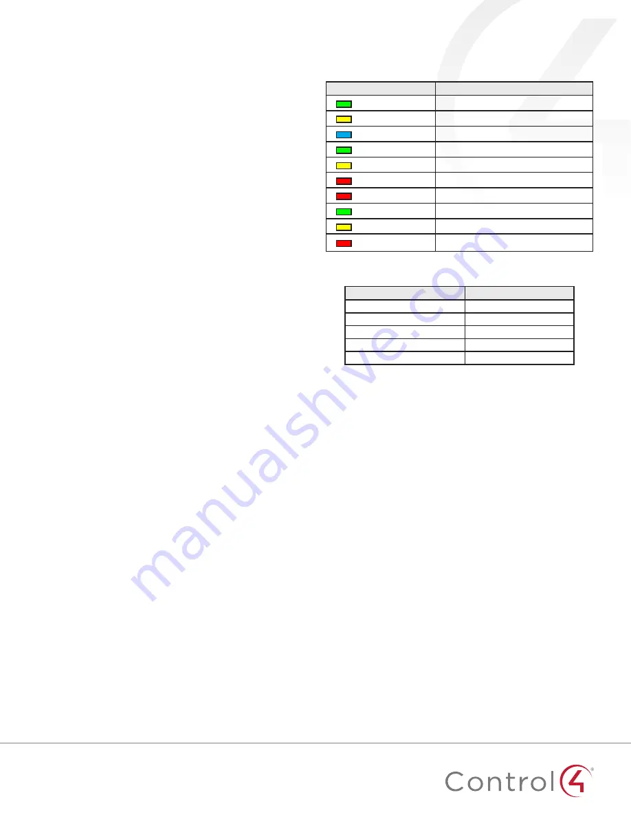
LED diagnostics
The indicated statuses appear during device identification and when
the ID button is pressed once.
LED
Description
[Green] On
Offline/Waiting for Director
[Yellow] Slow flashing
Scanning
[Blue] On
Join success
[Green] Fast flashing
Join success signal strength=good
[Yellow] Fast flashing
Join success signal strength=adequate
[Red] Fast flashing
Join success signal strength=risk/low
[Red] Medium flashing
Join failed (then returns to offline)
[Green] Slow flashing
Signal strength=good (from Network Tools)
[Yellow] Slow flashing
Signal strength=adequate (from Network Tools)
[Red] Slow flashing
Signal strength=risk/low (from Network Tools)
Button sequences
Functions
# of button presses
Identify
4
Reboot/Reset
15
Reset application defaults
9
Leave mesh, restore factory defaults
13
Signal strength flash LEDs
1
Restoring to previous firmware version
1
Power off the device (disconnect power).
2
While holding down the
ID
button, reconnect power, and continue
to press the
ID
button until the LED changes from red to white
(about five seconds).
3
Release the button. The device will reboot to its previous firmware
version in about one minute.


