Contrive FIRO Manual Download Page 8

© 2020 

CONTRIVE • B14

33|FIRO.EN 

1020


8


www.contrive.it 

GAS BURNER 


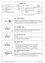
The burner is turned ON/OFF together with device power supply.  

A flame simulation test is carried out during pre-purge (waiting time). 

The fuel valve 

[V] 

will be activated only if the ignition output is detected during pre-ignition time. 

The fuel valve remains open during the programmed safety time, if a valid flame signal is detected within the safety 

time, the valve is kept open: the burner is ON. If no flame is detected the system will lockout. 

In accordance with EN746

-

2 and EN676, up to 4 ignition attempts are allowed if the safety is not impaired. 


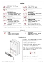
Push the front panel button to reset from lockout (will take place at release). 

Flame quenching during burner operation will force the system to lockout, recycle or ignition restoration. 

To put the burner out of service (manual shutdown) push the front panel button during the operating cycle.  

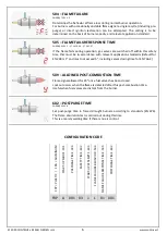
A post-combustion time (max 20 seconds) is allowed after a lockout or shutdown request, followed by post-purge. 

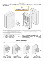
It is possible to share a single rod for ignition and flame detection using special ignition transformers. 
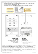


THERMOSTAT 


GAS VALVE 


K


POWER RELAY 


SINGLE ROD CIRCUIT 

M


BLOWER


DUAL ROD CIRCUIT 


LOW AIR PRESSURE SWITCH 


BURNER LOCKOUT


RESET INPUT 


ALL SAF

ETY SWITCHES SHOULD BE APPROVED AS LIMIT CONTROLS


THE USE OF ELECTRONIC SWITCHES MAY CAUSE ERRATIC OPERATIONS


Summary of Contents for FIRO

Page 1: ...y devices The device is not user serviceable a faulty device must be put out of order and sent back for servicing CONTRIVE manufactures products used as components in a wide variety of industrial syst...

Page 2: ...RNAL NON REPLACEABLE 5A SAFETY FUSE STATUS DISPLAY 4 USE POWER SIGNAL AND CONTROL CABLE SUITABLE FOR THE TYPE OF OPERATION AND COMPLYING WITH ALL REGULATIONS DO NOT ROUTE CONNECTIONS TOGETHER WITH FRE...

Page 3: ...cation about the working conditions of both the burner and the equipment making it easier to detect any failure occurring in the system or the device LOCKOUTS STANDBY WAITING FOR RESET WHEN PROGRAMMED...

Page 4: ...OUTPUTS RELEASED RESET FAILURE PUSH BUTTON OR REMOTE RESET ACTIVE FOR LONG TIME MORE THAN 10 SECONDS 1 A PREMANENT FAILURE TO THE RELAY CONTACT MAY CAUSE THE MAIN FUSE TO BLOWN AS A SAFETY MEASURE TO...

Page 5: ...124 4 Set pre purge time in forced draught burners according to applicable and relevant standards EN 676 During this time the flame simulation test is carried out This is a merely waiting time if the...

Page 6: ...evant application standards default for EN 298 is 1 and must not exceed 5 including valves closing time for EN 746 2 509 ALLOWED POST COMBUSTION TIME Flame signal allowed for 20 once fuel valves has b...

Page 7: ...FOR PG9 CABLE GLANDS FRA CAST ALUMINUM ALLOY EN AB 46100 IP64 OVERALL DIMENSION 200 x 120 x 71 mm WEIGHT 850 g ELECTROSTATIC POLYESTER POWDER COATING RAL9006 FRP THERMOPLASTIC POLYMER BLEND UL V0 IP64...

Page 8: ...if the safety is not impaired Push the front panel button to reset from lockout will take place at release Flame quenching during burner operation will force the system to lockout recycle or ignition...

Page 9: ...Y II PURSUANT TO EN 60730 FLAME DETECTION MINIMUM IONIZATION CURRENT 1 A CURRENT LIMITATION 1 mA DETECTOR LINE LENGTH 30 m SINGLE ROD LINE LENGTH 2 m DETECTOR VOLTAGE 250 Vac DETECTOR INSULATION 50 M...

Reviews: