


© 2020
CONTRIVE • B1444
|FIRO.EN
10
20
6
www.contrive.it
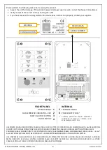
504 – FLAME FAILURE
EN298 §
7.101.2.3
Determines the behavior at flame loss during normal burner operation.
For burners with occasionally unstable flame signal a single recycle (including pre-
purge) or direct ignition restoration can be attempted. The setting is to be
determined on the basis of burner capacity and relevant application standard.
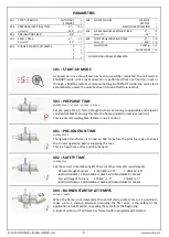
505 – FLAME FAILURE RESPONSE TIME
EN298 §
3.1
05.
1
-
§ 7.101.3.4.3
-
§ 7.101.3.7
If the flame fails during operation, gas valves are switched off within this safety
time that must be in accordance with relevant application standards (default for
EN 298 is 1” and must not exceed 5”
, including valves closing time fo
r EN 746
-2).
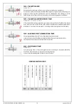
509 – ALLOWED POST-COMBUSTION TIME
Flame signal allowed for 20” once fuel valves has been closed.
Lockout occurs when the flame is detected after this post-combustion time.
Useful when fuel valves are distant from the burner.
602 – POSTPURGE TIME
EN298 §
3.124
.
6
Set post-
purge time in forced draught burners according to standards (EN 676).
The flame simulation test is carried out during this time.
This is a merely waiting time if there is no air control.
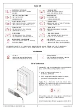
CONFIGURATION CODE
FR
P = P
LA
ST
IC
|
F
RA
=
A
LU
M
IN
UM
ST
AR
T-
UP
MO
DE
.
101
PR
EP
UR
GE T
IM
E .
3
03
SA
FE
TY TI
M
E .
4
02
ST
AR
T-
UP
A
TT
EM
PTS
.
40
3
FL
AM
E
FA
ILU
RE
B
EH
AVIO
R
. 5
04
FL
AM
E F
AI
LU
RE
R
ES
PON
SE
TI
M
E .
5
05
POS
TP
UR
GE
TI
M
E
. 6
02
FRP A
001
03
1
L
01
001


