


© 2020
CONTRIVE • B1444
|FIRO.EN
10
20
2
www.contrive.it
Please perform the following tasks after receiving the product:
•
Inspect the unit for damage. If the product appears damaged upon receipt, contact the shipper immediately.
•
Verify receipt of the correct unit by checking the label.
•
If you have received the wrong model or the device does not function properly, contact your supplier.
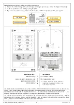
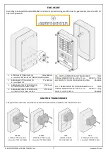
FRONT PANEL
INTERNAL
FITTING SCREWS
1
5
TERMINAL BOARD
FLAME PRESENCE INDICATOR – RED
2
6
POWER SUPPLY FUSE
1
RESET / SHUTOFF BUTTON
3
1
ULTIMATE PROTECTION AGAINST DANGEROUS
CONDITIONS BY MEANS OF
INTERNAL, NON
REPLACEABLE
5A SAFETY FUSE
STATUS DISPLAY
4
USE POWER, SIGNAL AN
D CONTROL CABLE SUITABLE FOR THE TYPE OF
OPERATION AND COMPLYING WITH ALL REGULATIONS
DO NOT ROUTE CONNECTIONS TOGETHER WITH FREQUENCY CONVERTER
CABLES OR CABLES EMI
TTING STRONG FIELDS
PROVIDE
RELIABLE CONNECTION
TO PE (PROTECTION EA
RTH) AND BURNER FRAM
E, RECOMMENDED WIRE GAUGE >
4
mm
2
ALL ELECTRONIC SYSTE
MS MUST BE SUPPLIED BY A DEDICATED TRANS
FORMER IN A TN-S EARTHING SYSTEM
USE UNSCREENED HIGH-
VOLTAGE CABLE FOR IG
NITION AND IONIZATION ROD LI
NES, LAYING CABLES I
NDIVIDUALLY, AVOIDING
METAL CONDUITS. KEEP HIGH VOLTAGE IG
NITION CABLES AS SHORT AS POSSIBLE, AVOI
DING LOOPS AND KEEP ALL OTHER
CABLES, ESPECIALLY T
HOSE OF IONIZATION ROD, AS FAR APART
AS POSSIBLE
DEVICE DATA
QR CODE
SERIAL NUMBER
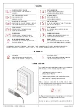
CONFIGURATION


