EMM-R3 VA
instruction manual
IM425-U v2.0
pag. 3
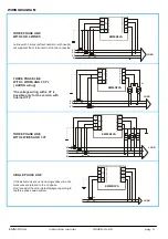
WIRING DIAGRAM
P1
P1
P1
P2
S1
S1
S1
S2
N
L1
L2
L3
I2
C.I.
I1
I3
S1
S2
V
L1
V
L2
V
L3
N
m
e
as
ur
e c
ur
re
nt
in
p
ut
s
m
eas
ur
e v
ol
tag
e
in
pu
ts
on lines with 3 wires (without neutral or with neutral
not supplied) the N terminal must not be connected
THREE PHASE LINE
WITH 3 OR 4 WIRES
P1
S1
S1
S2
L1
L2
L3
THREE PHASE LINE
WITH 3 WIRES AND 2 CT’s
( AARON wiring)
*the voltage wiring with 2 VT is
possible only for the version with
internal CT’s
P1
P2
S2
P2
P1
P1
P1
P2
S1
S1
S1
S2
N
L1
L2
L3
THREE PHASE LINE
WITH 4 WIRES AND 3 VT
P1
P2
S1
S2
N
L
SINGLE PHASE LINE
If the instruments are used on single phase line, the
measures are referred to the L3 phase.
Don’t consider the other data displayed regarding to
the three phase value system.
LOAD
I2
C.I.
I1
I3
S1
S2
V
L1
V
L2
V
L3
N
m
eas
ur
e c
urr
e
nt
in
pu
ts
m
e
as
ur
e v
ol
ta
ge
in
p
ut
s
EMM-R3VA
I2
C.I.
I1
I3
S1
S2
V
L1
V
L2
V
L3
N
m
e
as
u
re
c
u
rr
en
t i
n
pu
ts
m
e
as
u
re
v
o
ltag
e
in
p
ut
s
I2
C.I.
I1
I3
S1
S2
V
L1
V
L2
V
L3
N
m
eas
ur
e c
u
rr
en
t i
n
pu
ts
m
eas
ur
e v
o
lta
g
e i
n
pu
ts
*
EMM-R3VA
LOAD
EMM-R3VA
LOAD
EMM-R3VA
LOAD


