EMM-R3 VA
instruction manual
IM425-U v2.0
pag. 2
INSTALLATION
WARNING FOR THE USER
Read carefully the instructions/indications contained in this manual before installing and using the instrument.
The instrument described in this manual is intended for use by properly trained staff only.
SAFETY
This instrument has been manufactured and tested in compliance with EN 61010-1 standards. In order to maintain these conditions and
to ensure safe operation, the person must comply with the indications and markings contained in the manual. When the instrument is
received, before beginning installation, check that it's OK And it has not suffered any damage during transport. When starting
installations make sure that the operating voltage and mains voltages are compatible with the device instructions. The instrument power
supply must not be earthen. Only qualified and authorised personnel must carry out maintenance and/or repair. If there is ever the
suspicious that, that there is a lack of safety, during operation, the instrument must be disconnected and cautions taken against
accidental use.
Operation is no longer safe when: The instrument doesn't work. - There is clearly visible damage. - After serious damage
incurred during transport. - After a storage under unfavourable conditions.
WIRING
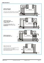
For a correct use of the device, the wiring diagram contained in the present manual must be respected.
The connections are available on the screw terminal:
- Auxiliary power supply:
The power supply is take from voltage inputs.
There are 3 different auxiliary supplies:
Vn 110V = 100-125V 50-60Hz
Vn 230V = 220-240V 50-60Hz
Vn 400V = 380-415V 50-60Hz
In the standard version the voltage is 400V and it’s taken between the phases L2-L3.
In the following table it’s possible to see the measurable voltage depending of the type of power supply.
Power supply terminals
Rated voltage
Range of measurable voltage
400V
300÷500V phase to phase (175÷290V phase-neutral)
230V
175÷290V phase to phase (130÷170V phase-neutral)
L2-L3
(phase to phase power supply)
110V
85÷145V phase to phase (50÷85V phase-neutral)
230V
300÷500V phase to phase (175÷290V phase-neutral)
L3-N
(phase – neutral power supply)
110V
175÷290V phase to phase (100÷170V phase-neutral)
The standard version allows applying the instrument at all the three-phase network 400V with or without neutral supplied.
For example for application on single phase 230V it will need the L3-N / 230V. While for applications in medium voltage
(for example using external voltage transformer 15 / 0.1 kV phase to phase) it will need the version L2-L3 / 110V.
- measuring voltage inputs:
4 terminals are available for the connection to the 3 phase and
neutral of the measuring network, the maximum voltage phase to
phase shouldn't be over 500 V rms and it will always be depending
on the auxiliary power supply.
In case of a 3 phase system without neutral, or non-distributed
neutral, to leave terminal N free.
It’s possible to use external voltage transformer. In fact the
transformation rate of the external transducer can be set in the
SETUP of the instrument and the visualisation allows the reading of
voltage up to 40,0 kV.
- measuring current inputs:
4 terminals are available for the connection to 3 external CT’s with
secondary 5A, it’s possible to use 2 CT’s on 3 wires system (three
phases Aaron wiring). The use of external CT’s is always necessary.
The transformation rate of the external transducer can be set in the
SETUP of the instrument and the visualisation allows the reading of
voltage up to 9,99 kA.
NOTE: It's a must to respect the phase sequence. The connections between current and voltage phase inputs must not be inverted (for
example, CT placed on phase L1 must correspond to the I1 input). So as it is not correct to invert S1 and S2 terminals.
To fix the device at the panel, insert the two brackets into their corresponding grove holes, at the side of the enclosure and fix up the
screws. It’s better to put an external protection with fuses for the voltage inputs and to use adapted cables for the working currents and
voltages: section from 0.5 to 2.5 mm
2
.
ENERGY COUNTERS
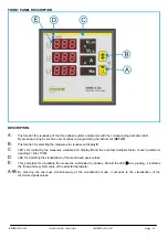
PANNELLO POSTERIORE (lato connessioni)
morsettiera a vite


