Continental Hydraulics CEM-SA-B Installation Manual Download Page 13


Continental Hydraulics Installation Manual 


Page 13 of 27 

CEM-SA-B 

CHI 1020687   01/2016 


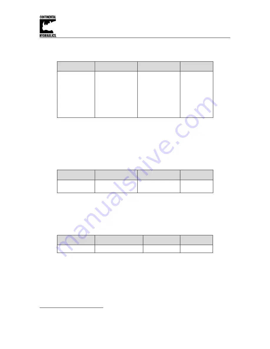
SIGNAL (Type of input) 


Command 

Parameter 

Unit 

Group 

SIGNAL:i    x 

i= 

W|X|V 

x=  

OFF 


U0-10 


U10-0 


I4-20 


I20-4 

EASY 

 
This command can be used to change the type of input signal (voltages or current) and to define 
the direction of the signal. This command is available for all analog inputs (W, X, and V).  
OFF= Deactivation of the input

2

See 

ANIMODE

 section (page 24-25) if the Signals used are not listed above, for re-scaling as 

required. 
 

N_RANGE: X (Nominal range of the sensor) 


Command 

Parameter 

Unit 

Group 

N_RANGE:X 
 

x= 10… 10000 

mm 

EASY 

 
N_RANGE (nominal range or nominal stroke) is used to define the length of the sensor. This 
value should be always higher than SYS_RANGE. The control parameter cannot be calculated 
correctly in case of wrong values.  
 

OFFSET: X (Sensor offset) 


Command 

Parameter 

Unit 

Group 

OFFSET:X   x 

x= -

100000… 100000  µm 

EASY 

 
Adjustment of the zero point of the sensor. 


2

 The deactivation can be used to deactivate the velocity (speed) input PIN_9/10 (the VELO value is active).  

Summary of Contents for CEM-SA-B

Page 1: ...red The optimized control function offers a high degree of precision together with high stability for hydraulic drives The movement cycle is controlled via the external position and speed inputs The high resolution of the analogue signals ensures good positioning behavior A wide range of analog signals are accepted User may select either voltage or current input mode These inputs are easily scaled...

Page 2: ...LED Indications 9 Command Parameter Descriptions LG Language 10 MODE 10 SENS 10 EOUT 11 ENABLE 11 START RUN 11 HAND A HAND B 12 INPOS 12 SYS_RANGE 12 SIGNAL W X V 13 N_RANGE X 13 OFFSET X 13 Using SYS_RANGE N_RANGE and OFFSET 14 Speed Commands SIGNAL V 15 VELO 15 VRAMP 15 VMODE 16 ACCEL 16 VMAX 16 A A and A B 17 D A D B D S 17 V0 A V0 B V0 RES 18 PT1 18 CTRL 19 MIN A MIN B 20 MAX A MAX B 20 TRIGGE...

Page 3: ...put V 0 10 90 kOhm mA 4 20 240 Ohm 0 003 Analogue outputs Voltage V 2 x 0 10 differential output mA 10 max load Signal resolution 0 006 Current mA 4 20 390 Ohm maximum load Signal resolution 0 006 Controller sample time ms 1 USB in RS 232C Emulation 9600 57600 Baud 1 stop bit no parity echo mode Snap on module to EN 50022 PA 6 6 polyamide Flammability class V0 UL94 Weight kg 0 170 Protection class...

Page 4: ...Wiring Example Power Supply 15 16 Differential Input on Control Valve 3 4 12 1 2 Ready In Pos 5 Start Run Hand jog 6 7 8 Hand jog Analog Position Feedback Analog Command Position Analog Speed optional 24v 14 11 13 11 10 9 Gnd 24v Gnd Valve out Enable Speed Command Feedback Valve out Dimensions 4 5 3 9 0 9 ...

Page 5: ...UT command START RUN input The position controller is active and the external analogue demand position is accepted as the demand value If the input is disabled during the movement the system is stopped within the set emergency stopping distance D S HAND input Manual operation START OFF the drive moves at the programmed speed in the programmed direction After deactivation the actual current positio...

Page 6: ...rosoft Windows application 1 Mount the module in a suitable location 2 Connect the power supply and valve solenoids 3 Down load and open the GUI program www continentalhydraulics com wp content uploads 2015 01 setup CEWMPC 10 v3 5 0 zip 4 Connect to Laptop via USB to USB Type B communication cable 5 Open the Options and check setting make sure the correct com port full Duplex and 57 6K Baud rate a...

Page 7: ...e solenoid voltage rating to power supply typically 12 or 24 volts A 1 amp medium action fuse is recommended in the power supply line Wiring to Valve Two conductors are required for each solenoid There is no need for shielding on these power conductors Wire size is chosen to provide an acceptable voltage drop between the module and the valve solenoid The following chart is based on 5 drop for 12v ...

Page 8: ... X 16 ACCEL 250 Acceleration mm s 2 X 16 VMAX 50 Maximum speed mm s X 17 A A 100 Acceleration time ms X X 17 A B 100 Acceleration time ms X X 17 D A 25 Deceleration stroke mm X X 17 D B 25 Deceleration stroke mm X X 17 D S 10 Overtravel mm X X 18 V0 A 25 Loop gain 1 s X 18 V0 B 25 Loop gain 1 s X 18 V0 RES 1 Loop gain resolution X 18 PT1 1 PR1 filter time constant ms X X 19 CTRL SQRT1 Control char...

Page 9: ... are possible 2 All LEDs flash shortly every 6 s An internal data error was detected and corrected automatically The module still works regularly To acknowledge the error the module has to have power cycled YELLOW A YELLOW B Both yellow LEDs flash oppositely every 1 s The nonvolatile stored parameters are inconsistent To acknowledge the error the data have to be saved with the SAVE command or the ...

Page 10: ...vior and should accordingly be changed with care see page 8 SENS monitoring of the modul functions Command Parameters Unit Group SENS x x ON OFF AUTO STD This command is used to activate deactivate the monitoring functions 4 20 mA sensors output current signal range and internal failures of the module ON All monitoring functions are active Detected failures can be reset by deactivating the ENABLE ...

Page 11: ...alyzed by the user for each application from the point of view of safety Do not use the manual mode in conjunction with the EOUT command After the deactivation of the HAND input the output is set to the EOUT value ENABLE pin 8 digital input ENABLE is a digital input that is active high When the ENABLE input is low there is no output to the valve Command input and feedback input values are ignored ...

Page 12: ...he internal or external speed demand MIN evaluation Caution Do not use the manual mode in conjunction with the EOUT command After the deactivation of the HAND input the output is set to the EOUT value INPOS In position range Command Parameters Unit Group INPOS x x 2 200000 µm STD This parameter is entered in µm The INPOS command defines a range for which the INPOS message is generated This functio...

Page 13: ... page 24 25 if the Signals used are not listed above for re scaling as required N_RANGE X Nominal range of the sensor Command Parameter Unit Group N_RANGE X x x 10 10000 mm EASY N_RANGE nominal range or nominal stroke is used to define the length of the sensor This value should be always higher than SYS_RANGE The control parameter cannot be calculated correctly in case of wrong values OFFSET X Sen...

Page 14: ...nd OFFSET X must be scaled to match The application scaling will be done by these three commands In this example Figure 1 the system is defined by a length of 120 mm of the sensor a working stroke of 100 mm of the cylinder and an offset of 5 mm These parameters have to be typed in and the axis is driving between 5 mm and 105 mm of the sensor stroke and between 0 mm and 100 mm of the cylinder strok...

Page 15: ... scaling as required VELO Internal speed demand value Command Parameters Unit Group VELO x x 1 10000 0 01 SIGNAL V OFF Specification of the internal speed limitation VRAMP Ramp time for external speed demand Command Parameters Unit Group VRAMP x x 10 5000 ms SIGNAL V The rate of change of the external speed demand can be limited by this ramp time The command is only active if external speed demand...

Page 16: ...the following error to follow the position profile The magnitude of the following error is determined by the dynamics and the closed loop gain The advantage is that the speed is constant regardless of external influences due to the profile demand Because of continuous control it is necessary to run at less than 100 speed as otherwise the errors cannot be corrected 70 80 of the maximum speed is typ...

Page 17: ...t for each direction of movement A or B The control gain is calculated internally depending on the deceleration distance The shorter the deceleration distance the higher the gain A longer deceleration distance should be specified in the event of instability Parameter D S is used as the stopping ramp when disabling the START PIN 7 signal After disabling a new target position current position plus D...

Page 18: ...e relationship described here is taken into account V0 RES Scaling of the loop gain Command Parameters Unit Group V0 RES x x 1 100 VMODE NC V0 RES 1 loop gain in s 1 1 s units V0 RES 100 loop gain in 0 01 s 1 units6 The increased resolution should be used in case of V0 4 PT1 Timing of the controller Command Parameter Unit Group PT1 x x 0 300 ms EXP This parameter can be used to change the internal...

Page 19: ...t can also lead to longer positioning times in individual cases LIN Linear deceleration characteristic gain is increased by a factor of 1 SQRT1 Root function for braking curve calculation The gain is increased by a factor of 3 in the target position This is the default setting SQRT2 Root function for braking curve calculation The gain is increased by a factor of 5 in the target position This setti...

Page 20: ...justment is performed either at the power amplifier or in the module If the MIN value is set too high this has an effect on the minimum speed which can then no longer be adjusted In extreme cases this leads to oscillation around the controlled position MAX A MIN A MIN B MAX B Input Output non lineare Flow compensation Standard deadband compensation TRIGGER 8 Various manufacturers have valves with ...

Page 21: ...o define the output signal voltage or current and to change the polarity9 Differential output 100 corresponds with 10 V 0 10 V at PIN 15 and PIN 16 Current output 100 corresponds with 4 20 mA PIN 15 to PIN 12 12 mA 0 center point of the valve An output current of 4 mA indicates an error and the module is disabled The current input of the proportional valves should be monitored by the valve The val...

Page 22: ...nal can vary cycle to cycle How does it work High accurate positioning These kinds of position errors should be compensated when the axis is near by the target position The output signal is going lower and lower but a system specific position error remains At the activation point this function a slowly working integrator is active This integrator signal is added to the output signal and will compe...

Page 23: ...n state DC AV 0 should be used for best positioning but limit cycling can occur This value should be set to 50 of an acceptable error DC I This parameter is used to define the integrator time The lower this value the faster the compensation Low values will result in limit cycling DC CR the output range of the DC function will be limited CR control range by this parameter PROCESS DATA Monitoring Co...

Page 24: ...he input signal being used are not as listed the AINMODE is available in the MATH mode where the input signals can be scaled by a linear equation To enter the MATH option you must change the AINMODE to MATH by use of the Terminal Window see steps 1 4 below Once in the Termainal Window screen type in AINMODE MATH and click the Save button At this time you may go back to the Parameter screen where y...

Page 25: ... In the case of a 4 20mA with a single solenoid valve the total range is 0 20mA which means A 20 The actual range is 4 20 mA therefore B 20 4 16 An offset C must be added to compensate for the 0 4mA not being used of the full range The offset is 4mA 20mA 0 2 or 20 Therefore C 2000 since the unit value for C is 0 01 Shown in the below table are the most common input command signal and the correspon...

Page 26: ...e parameterized Internal data error press the command SAVE button to delete the data error The system reloads the DEFAULT data With the CHI PC operating program the fault can be localized directly via the monitor ENABLE is active the READY LED is on the system moves to an end position The control circuit polarity is incorrect The polarity can be changed with the POL command or by reversing the con...

Page 27: ... and D B and in the case of overlapped valves the MIN parameter should also be reduced Speed too low The drive may be able to move to position but the speed is too low Check the control signal to the valve Via the integrated oscilloscope U variable Measure the signal to the valve with an external oscilloscope voltmeter If the control is within the range of 100 10 V the fault must be sought in the ...

Reviews: