background image

English

DART60i

 - 60W 4-in-1 beam moving head with infinity move

Page 5

5 - Cabling, addressing and daisy chaining

Connecting the DMX remote control : 
Connect the female plug of your XLR cable to your DMX remote control XLR output, then connect your cable male output to the 
moving head. Daisy chain your moving heads with XLR cables.

1

2

R

3

120 

Ω

 1/4W

Using a DMX line termination :

When long runs of cable are used (more than 100m, you may need to use a terminator on the last unit to 
avoid erratic behavior. A terminator is a 110-120 ohm 1/4 watt resistor which is connected between pins 
2 and 3 of a male XLR connector. This unit is inserted in the female XLR connector of the last unit in your 
daisy chain to terminate the line.

Addressing the units :


Every unit must have a DMX address in order to respond to DMX signals. The address corresponds to the 
channel number on which the unit receives an incoming DMX signal sent by the DMX remote control.  The DMX addressing can be 
performed by programming the channel number via the display located on the base of the unit. 
You can either assign the same address to your units so they all react to the same signal, or assign a unique address per unit to 
control them independently.

In the example above, the DART60i uses 15 channels (standard mode).
You must skip 15 channels between each address you assign.
The address of the first unit will be 1, the second unit will be 16 (1+15), the third unit will be 31 (17+16) and so on. 

NB : Once switched on, the DART60i automatically detects any incoming DMX signal and the display indicates the unit DMX address. 
If the unit does not receive any DMX signal, the display will flash. In such a case, please make sure the cable is properly plugged into 
the DMX input of your moving head, your remote control is switched on and the cables used are not defective.

Daisy chaining :

The POWERCON© input/output system allows you to daisy chain several DART60i units.

Warning: You cannot use the same chain to supply more than 10 DART60i at 220V.

When using a 11th moving head, please use a new power source.

Address 1

Address 11

Address 21

Summary of Contents for DART60i

Page 1: ...USER GUIDE 10490 Version 1 06 2016 60W 4 IN 1 BEAM MOVING HEAD WITH INFINITY MOVE...

Page 2: ...in electric shock or fire Never spill any liquid on this product as it may infiltrate the electronic components and result in electric shock or fire 15 This product should be serviced when Please con...

Page 3: ...n musical and auto programs Automatic detection of the DMX slave or master mode Colour LCD drop down menu to choose and assign the different modes Battery operated memory system to address and choose...

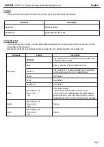
Page 4: ...utrik socket 4 Description 1 Bar with lenses 2 Display Allows you to visualise menus 3 DC SWITCH button Switches the menu on when the moving head is not plugged in 4 ENTER button Selects functions and...

Page 5: ...DMX addressing can be performed by programming the channel number via the display located on the base of the unit You can either assign the same address to your units so they all react to the same si...

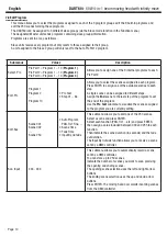
Page 6: ...for more than 2 seconds If the buttons are not used and remain inactive for 1 minute the display will automatically turn off When browsing through menus values in blue are values currently in use Whe...

Page 7: ...the projector head C Software V 1U01 V1 03 2U01 V1 03 3U01 V1 03 4U01 V1 03 Current version of the internal software Model Info FLAG25i Displays the name of your product Error Info Pan Tilt Displays...

Page 8: ...les valeurs suivantes 50 75 ou 90 LCD Set Shutoff time 02 60m 05m Timer after which the display shuts off when it remains inactive Display Reverse ON OFF Rotates the display on a 180 angle Key Lock O...

Page 9: ...and TILT motors Submenus Values Description User Mode Standard This default mode uses 19 DMX channels with the most frequently used functions Basic Uses 10 channels this is the simplest mode MDOT ST...

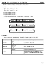
Page 10: ...NTER to assign one of the available scenes to each step A single scene can be assigned to different steps Assign the End scene to the last step of the program to set the end of the program Use the Pro...

Page 11: ...programs according to the same number of steps as follows Scene 10 Scene 11 Scene 12 Scene 13 Scene 8 Scene 9 Scene 10 Scene 8 Scene 12 Scene 13 Scene 14 Scene 15 This menu allows you to test and man...

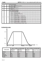
Page 12: ...226 235 Black out during movements 236 255 No function max speed 6 4 6 Non stop PAN movement 000 127 No function 128 189 Clockwise fast to slow rotation 190 193 No rotation 194 255 Counterclockwise s...

Page 13: ...9 Yellow 040 044 Magenta 045 049 Cyan 050 054 Salmon 055 059 Turquoise 060 064 Light green 065 069 Steel blue 070 074 Orange 075 079 Straw 080 084 Light lavender 085 089 Pink 090 094 Green 095 099 Red...

Page 14: ...t in program 3 Scenes from 17 to 24 160 179 Built in program 4 Scenes from 25 to 32 180 199 Built in program 5 Scenes from 33 to 40 200 219 Built in program 6 Scenes from 41 to 48 220 239 Built in pro...

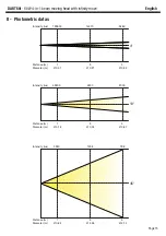
Page 15: ...ove Page 15 8 Photometric datas Distance m Diameter m 4 10 1 3 5 0 07 0 21 0 35 Distance m Diameter m 1 3 5 0 18 0 52 0 87 Intensity lux 122600 14570 5280 Intensity lux 42800 4300 2000 45 Distance m D...

Page 16: ...PAN movement error yoke This message will appear upon initialisation if the PAN position magnetic sensor of your device is defective Error channel is 06 TILT movement error head This message will app...

Page 17: ...English DART60i 60W 4 in 1 beam moving head with infinity move Page 17...

Page 18: ...s to modifications without prior notice That is why technical specifications and the products physical configuration might differ from the illustrations Make sure you get the latest news and updates a...

Reviews: