background image


Revision History 

MONTH YEAR 

Summary of Changes 

August 2017 

The First Edition 

June 2018 

The details of the function were added. 


COM-2PD-LPE 

User’s Guide


CONTEC CO., LTD.


June 2018 Edition


3-9-31, Himesato, Nishiyodogawa-ku, Osaka 555-0025, Japan 
https://www.contec.com/ 


No part of this document may be copied or reproduced in any form by any means without prior written 

consent of CONTEC CO., LTD.     

[06112018] 

[08242017] 

Management No. 

NA05875 

[06052018_rev2] 

Parts No. 

LYVJ372 

Summary of Contents for COM-2PD-LPE

Page 1: ...PC HELPER RS 422A 485 2ch Serial I O Board with Isolation for PCI Express Low Profile COM 2PD LPE User s Guide CONTEC CO LTD ...

Page 2: ...ing items contact your retailer Product Configuration List Board COM 2PD LPE 1 First step guide 1 Disk 1 COM Setup Disk 1 Standard size bracket 1 Warranty Certificate 1 Serial Number Label 1 1 The bundled disk contains the driver software and User s Guide this guide COM 2PD LPE First step guide First step guide Serial Number Label Warranty Certificate Warranty Certificate Standard size bracket Dis...

Page 3: ...ange without notice All relevant issues have been considered in the preparation of this document Should you notice an omission or any questionable item in this document please feel free to notify CONTEC CO LTD Regardless of the foregoing statement CONTEC assumes no responsibility for any errors that may appear in this document or for results obtained by the user as a result of using this product T...

Page 4: ...ironment 8 Inspection 8 Storage 8 Disposal 8 2 SETUP 9 What is Setup 9 Using the Board under Windows Using the Standard COM Driver Software COM Setup Disk 9 Using the Board under an OS Other than Windows 9 Step 1 Setting the Hardware 10 Replacing the Bracket 10 Parts of the Board and Factory Defaults 11 Setting the Board ID 11 Setting Transmission Mode 12 Setting of Terminator 13 Plugging the Boar...

Page 5: ... connector 28 Types of Cable and Example Connections 29 4 FUNCTIONS 31 Communication Function 31 Serial Data Transmission 31 RS 422A 485 Control Lines 31 Send and Receive Data Buffers 31 Setting the Baud Rate 32 Automatic RTS Control Functions 33 Other Functions 33 Channel Isolation Bus Isolation 33 Surge Protection 33 5 ABOUT SOFTWARE 35 About Sample programs 35 Uninstalling the driver software 3...

Page 6: ...bly used as Windows standard COM ports using the bundled driver library Comes with a driver software that allows the products to be used under Windows in the same way as COM ports on the PC Under Windows the product supports the OS standard Win32 API communication function as well as Visual Basic MSComm In addition supplies a diagnostic program to confirm hardware operation and to perform a commun...

Page 7: ...igger size you can build an optimum system according to your use Support for Low Profile size slot standard size slot Bundled with each bracket for Low Profile size slot standard size slot Exchanges it for the standard size bracket when mounting on the standard size slot To suit your application cables and connectors are available as optional Distribution cable for 2channels and 44 pin D SUB conne...

Page 8: ...l communications such as for remote access service RAS and uninterruptible power supply UPS applications Under Windows the serial ports can be accessed using the standard Win32 API communication routines CreateFile WriteFile ReadFile and SetCommState etc The serial ports are also compatible with the Visual Basic communication control MSComm Supports the communication class of NET Framework 2 0 Ser...

Page 9: ...d freight prepaid with a copy of the original invoice and a Return Merchandise Authorization to the distributor or the CONTEC group office from which it was purchased This warranty is not applicable for scratches or normal wear but only for the electronic circuitry and original boards The warranty is not applicable if the device has been tampered with or damaged through abuse mistreatment neglect ...

Page 10: ...struction of equipment and resources Understand the meanings of these labels to operate the equipment safely DANGER indicates an imminently hazardous situation which if not avoided will result in death or serious injury WARNING indicates a potentially hazardous situation which if not avoided could result in death or serious injury CAUTION indicates a potentially hazardous situation which if not av...

Page 11: ...s with industrial alcohol Do not install or remove the board to or from the slot while the computer s power is turned on Otherwise the board may malfunction overheat or cause a failure Be sure that the personal computer or the I O expansion unit power is turned off Make sure that your PC or expansion unit can supply ample power to all the boards installed Insufficiently energized boards could malf...

Page 12: ...y and if not installed and used in accordance with the instruction manual may cause harmful interference to radio communications Operation of this equipment in a residential area is likely to cause harmful interference in which case the user will be required to correct the interference at his own expense NOTE FCC WARNING Changes or modifications not expressly approved by the party responsible for ...

Page 13: ...g this product keep it in its original packing form 1 Put the board in the storage bag 2 Wrap it in the packing material then put it in the box 3 Store the package at room temperature at a place free from direct sunlight moisture shock vibration magnetism and static electricity Disposal When disposing of the product follow the disposal procedures stipulated under the relevant laws and municipal or...

Page 14: ... Setup Disk Taking the following steps sets up the software and hardware You can use the diagnosis program later to check whether the software and hardware function normally Step 1 Setting the Hardware Step 2 Installing the Hardware Step 3 Initializing the Software On the bundled disk refer to the PCI Readmee txt file and the installation instructions files for each OS located in the PCI InstDoc I...

Page 15: ...an expansion slot The board can be set up even with the factory defaults untouched You can change board settings later Replacing the Bracket This board is shipped with a Low Profile size bracket mounted To plug the board into a standard size slot replace the bracket with the bundled standard size bracket The replacing method is as follows Figure 2 1 Replacing the Bracket Low Profilesize bracket At...

Page 16: ...om 0 Fh to identify up to sixteen boards If only one board is used the original factory setting Board ID 0 should be used Setting Procedure To set the board ID use the rotary switch on the board Turn the SW1 using for example a standard screwdriver to set the arrow to the board ID Figure 2 3 Board ID Settings SW1 SW1 BOARD ID COM 2PD LPE SW1 BOARD ID Board ID setting SW SW1 0 D E F 8 Interface con...

Page 17: ...not use with bits 1 and 2 both set ON as this may result in damage to the board Transmission mode Setting method Half duplex When there are no RTS and CTS To connect RTS and CTS to the other unit communication is available TXD is only used for data transmission the sending and receiving modes should be switched over using the modem control register Full duplex RTS CTS When there are RTS and CTS RT...

Page 18: ...w examples of terminator installation for half and full duplex setting Table 2 2 Setting of Terminator Falf duplex Figure 2 4 Multi Drop Connection Inserted Not inserted Figure 2 4 A or D Both terminators of the line Setting method Term ON Term OFF Factory setting Figure 2 4 B or C Other than both terminators of the line SW2 SW3 MODE TERM RxD TxD CTS RTS ON 1 2 3 4 5 6 7 8 9 10 SW2 SW3 MODE TERM R...

Page 19: ...ODE TERM RxD TxD CTS RTS SW2 SW3 MODE TERM RxD TxD CTS RTS Set the RTS CTS terminator to OFF ON 1 2 3 4 5 6 7 8 9 10 ON 1 2 3 4 5 6 7 8 9 10 RxD TxD Terminator Bit9 Terminator Bit7 Terminator Bit7 Terminator Bit9 TxD RxD CTS RTS Terminator Bit0 Terminator Bit8 Terminator Bit8 Terminator Bit0 CTS Not inserted Inserted SW2 SW3 MODE TERM RxD TxD CTS RTS SW2 SW3 MODE TERM RxD TxD CTS RTS RTS ON 1 2 3 ...

Page 20: ... with the data transfer mode setting switch and terminator setting switch Figure 2 7 Setting Switch Circuits TxD TxD RxD RxD CTS CTS RTS RTS RTS DCD DTR DSR RI CTS SIN SOUT 162850 or equivalent to it Terminator 1 2W 100Ω 1 3 4 5 6 2 7 910 8 Terminator Data transfer mode ...

Page 21: ...ise the board may malfunction overheat or cause a failure If the terminals are touched by someone s hands clean the terminals with industrial alcohol Do not install or remove the board to or from the slot while the computer s power is turned on Otherwise the board may malfunction overheat or cause a failure Doing so could cause trouble Be sure that the personal computer or the I O expansion unit p...

Page 22: ... be properly installed unless the resources I O addresses and interrupt level for the board can be allocated Before attempting to install the board first determine what PC resources are free to use The resources used by each board do not depend on the location of the PCI Express bus slot or the board itself If you remove two or more boards that have already been installed and then remount one of t...

Page 23: ...oard is attached Click on the device PCI Serial Port or PCI Simple Communication Controller and open its properties by clicking the Properties button 1 Please search for Devices and Printers case of Windows 8 The category of the board you have just added is displayed PCI Serial Port or PCI Simple Communication Controller ...

Page 24: ...ate Driver button 3 The Driver Installation Wizard is open Click Browse my computer for driver software 4 Specify that folder on bundled disk which contains the setup information INF file to register the board Source folder PCI ComDrv You have now finished installing the hardware 1 2 The category of the board you have just added is displayed PCI Serial Port or PCI Simple Communications Controller ...

Page 25: ...dware installation 1 Select System from Control Panel and open Device Manager 2 Check that the names of the boards you are using are registered correctly in the Multifunction adapters folder 3 Similarly confirm that the COM ports have been added in the Ports folder ...

Page 26: ...ent number The COM ports are already assigned by the hardware installation step Run Device Manager as described below if you wish to view or modify the COM port settings Start Device Manager 1 Select System from Control Panel and start Device Manager 2 Check that the new COM ports are displayed in the Ports folder The name of the board you have just added is displayed COM 2PD LPE ...

Page 27: ...the Used Serial Mice support for the serial mouse devices is enabled You have now finished installing the initial setting of Software For Windows 2000 and later operating systems COM ports that are determined by the operating system to not be in use are assigned The COM ports are not assigned by the CONTEC device driver Therefore they may not be assigned starting from CH1 depending on your environ...

Page 28: ...erial board have been assigned in order Table 2 4 shows an example in which the four channels of the serial board have not been assigned in order Table 2 4 Assigned in order CH no I O range COM port no CH1 EF00 EF07 COM3 CH2 EF08 EF0F COM4 CH3 EF10 EF17 COM5 CH4 EF18 EF1F COM6 Table 2 5 Not assigned in order CH no I O range COM port no CH1 EF00 EF07 COM5 CH2 EF08 EF0F COM6 CH3 EF10 EF17 COM3 CH4 E...

Page 29: ...am provided with Windows Serial Communications Diagnostic Program CommChk exe Performs actual communications and indicates whether the results are correct or not error The following describes the procedure for testing using the serial communications diagnostic program CommChk exe Check Method If a cross cable is not available you can test communication using a single COM port by means of loopback ...

Page 30: ...OM Setup Specify the number of the COM port you wish to test If connecting two COM ports via a cross cable specify the respective COM ports in Device1 and Device2 When performing loopback communications on a single COM port set the same port number in both Device 1 and Device 2 Communication Settings Specify the Bits Second Data bits and other settings you wish to use ...

Page 31: ...o start the test using the specified conditions View test result The test result is displayed in the Message window A successful completion message appears if the test completed OK Setup Troubleshooting If your problem cannot be resolved Contact your retailer ...

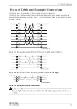
Page 32: ...ng into two 9 pin D SUB male connector channels Figure 3 1 Specification of PCE44 9P2S Connection conversion Option Connection Conversion Cable 44M 9M x 2 250mm PCE44 9P2S The SG lines for CH1 CH2 of the option cable are not connected to the cable shielding However the frame of each connector is connected to the shielding This means that the cable shielding is connected to the body of the PC via t...

Page 33: ...D1 28 CTS1 13 TxD1 41 N C 27 N C 12 N C 40 SG2 26 CTS2 11 RxD2 39 RTS2 25 RTS2 10 RxD2 38 TxD2 24 CTS2 9 TxD2 37 N C 23 N C 8 N C 36 N C 22 N C 7 N C 35 N C 21 N C 6 N C 34 N C 20 N C 5 N C 33 N C 19 N C 4 N C 32 N C 18 N C 3 N C 31 N C 17 N C 2 N C 16 N C 1 N C Figure 3 3 Pin Assignments of Interface Connector 44 31 15 1 30 16 Screw nut UNC 4 40 inch screw Connector used 44 pin D SUB female conne...

Page 34: ...mended to improve resistance to noise Figure 3 4 Example Connection RTS and CTS to a External Device in Full Duplex Figure 3 5 Example Connection Oneself loop to RTS and CTS in Full Duplex Figure 3 6 Example Connection in Half Duplex If connecting between external devices and this board with faulty wiring it will become the cause of failure RTS RxD TxD TxD RxD RTS CTS CTS SG RTS RxD TxD TxD RxD RT...

Page 35: ...3 External Connection 30 COM 2PD LPE ...

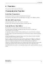
Page 36: ... OFF and FIFO trigger size are set by the Device Manager The FIFO trigger size specifies the data buffer size and determines the timing for generating hardware interrupts Setting a large FIFO trigger size lightens the load on the CPU by reducing the number of hardware interrupts generated by sending or receiving data However as data is not actually sent or received until a certain amount of data h...

Page 37: ... 7 2 As the result contains a fractional part a setup error occurs Refer to the following baud rate setting examples Table 4 1 Baud Rate Generator Programming Table Output baud rate bps Setup error 30 50 75 110 0 026 134 5 0 058 150 300 600 1200 1800 2000 0 680 2400 3600 4800 7200 9600 14400 19200 28800 38400 57600 76800 115200 153600 230400 460800 921600 As Visual Basic s communication control MS...

Page 38: ...re In Visual Basic half duplex communication cannot be used via the communication control MSComm as MSComm does not support setting this function Other Functions Channel Isolation Bus Isolation The communication lines for each channel are electrically isolated from each other and from the PC As isolation is provided between channels as well as isolation of the bus this prevents electrical interfer...

Page 39: ...4 Functions 34 COM 2PD LPE ...

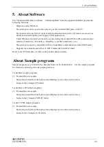
Page 40: ...ation control MSComm Supports the communication class of NET Framework SerialPort class Refer to the PCI Readmee txt files on the bundled disk for details About Sample programs Sample programs are provided in the Samples folder on the bundled disk Use the sample programs for reference and testing when developing software Visual Basic sample programs 1 Transmit Receive sample Sends data entered fro...

Page 41: ... C sample programs 1 Transmit sample Sends data entered from the keyboard Execute from the command prompt Source folder Samples Vc Comsend c file 2 Receive sample Displays received data on the screen Source folder Samples Vc Comread c file ...

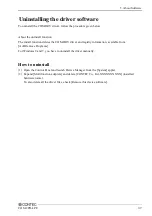
Page 42: ...e COM DRV driver and registry information available from Add Remove Programs For Windows 8 and 7 you have to uninstall the driver manually How to uninstall 1 Open the Control Panel and launch Device Manager from the System applet 2 Expand Multifunction adapters and delete CONTEC Co Ltd XXXXXXXXXX installed hardware name To also delete all the driver files check Remove this device software ...

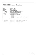
Page 43: ...ons for each OS Samples Various sample programs VB Sample program for Visual Basic VC Sample program for Visual C VB NET Sample program for VisualBasic NET for SerialPortClass VCS Sample program for VisualC NET for SerialPortClass USB USB related files UsersGuide Manual of hardware PDF UTILITY Various utilities CommChk Self diagnostic program Loopback communication test CTstCom Self diagnostic pro...

Page 44: ...are specifications and hardware related supplementary information For detailed technical information For further detailed technical information Technical Reference including the information such as an I O map configuration register etc visit the Contec s web site to call for it ...

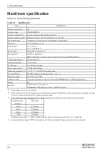
Page 45: ...C 600mA Max Operating temperature 0 50 C 10 90 RH No condensation Bus specification PCI Express Base Specification Rev 1 0a x 1 Dimension mm 121 69 L x 67 90 H Connector used 44 pin D SUB female connector 103A 44FGTBBB3 mfd by COXOC equivalent Weight 80g Standard VCCI Class A FCC Class A CE Marking EMC Directive Class A RoHS Directive 1 These items can be set by software 2 Data transmission at hig...

Page 46: ...6 About Hardware COM 2PD LPE 41 Board Dimensions mm 121 69 L 67 90 H The standard outside dimension L is the distance from the end of the board to the outer surface of the slot cover ...

Page 47: ...COM 2PD LPE User s Guide CONTEC CO LTD June 2018 Edition 3 9 31 Himesato Nishiyodogawa ku Osaka 555 0025 Japan https www contec com No part of this document may be copied or reproduced in any form by any means without prior written consent of CONTEC CO LTD 06112018 08242017 Management No NA05875 06052018_rev2 Parts No LYVJ372 ...

Reviews: