3. External Connection
CNT-3208M-PE
31
External Device Connection 1
-differential line receiver input-
Connecting the differential line receiver input
Use the differential line receiver input to connect the board to the line receiver output circuit of a rotary
encoder or linear scale. The maximum input frequency is 10 MHz.
For use in two-phase input mode, connect both of the phase-A and phase-B inputs. For use in single-
phase input mode, connect either of them. If phase-Z is not used, the input need not be connected.
For differential line receiver input mode, you can select whether to insert the terminal resistor.
Detailed description of differential line receiver input circuit
Figure 3.3. Differential line receiver input circuit and its sample connection
To protect the input circuit from voltage surges, a varistor is connected.
Figure 3.4. Input signal
-
In the input pin+, TTL level input circuit is parallel-connected.
-
Please use the shielded cable with a length of less than 30m to meet “CE EMC Directive”.
+5V
1k
Ω
51
Ω
150
Ω
51
Ω
1k
Ω
5VDC
ALS541
External power supply
Target equipment
Pulus
common
Equivalent
to 26LS31
Output
pin+
Output
pin-
Input
pin+
Input
pin-
Varistor
Board
Internal
circuit
Equivalent to 26LS32
Varistor
Ground
Minus
common
t
PWL
t
PWH : High-level count input pulse width 50nsec (Min.)
t
PWL : Low-level count input pulse width
50nsec (Min.)
t
PWH
CAUTION
Summary of Contents for CNT-3208M-PE
Page 7: ...vi CNT 3208M PE ...
Page 15: ...1 Before Using the Product 8 CNT 3208M PE ...
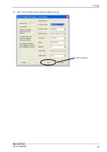
Page 30: ...2 Setup CNT 3208M PE 23 3 Click on the End button to finish condition setting Click on End ...
Page 35: ...2 Setup 28 CNT 3208M PE ...
Page 71: ...4 Functions 64 CNT 3208M PE ...


