


9
c)
c)
c)
c)
If the data storage function is turned on, when return to the measuring interface, a red
"REC"sign and a flashing red dot would appear on screen, which means the device is in a state of
record.
d)
d)
d)
d)
In the state of record,whatever interface the device is in (measuring interface, menu interface),
the sign "Recording" would appear on the screen in 30 seconds, then the screen will be automatically
shut down. If click the button at this moment, the sign "Recording" would appear on the screen, and
then the screen will be automatically shut down again; if press the button,the device would return to
the former interface.
e)
e)
e)
e)
If turning on the data storage function, the former saved data will be automatically deleted.
f)
f)
f)
f)
When recording, the pulse sound indication would be turned off for saving power, after the
screen is shut down automatically.
g)
g)
g)
g)
When the storage space is full, it displays “Memory is full” on the screen, and then shut down in
a few seconds. But it will still display “Memory is full” by the next time you turn on the device on
the purpose of warning the user, if press the button again, it will enter the measuring interface.
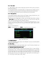
Figure 8
E
Set
Set
Set
Set Bluetooth
Bluetooth
Bluetooth
Bluetooth state
state
state
state
Move the menu selection bar to"Bluetooth" item,then press button to turn on/off Bluetooth.If there is
no data transmission,the Bluetooth will be closed 5 minutes later..
When
When
When
When the
the
the
the data
data
data
data is
is
is
is being
being
being
being transmitted
transmitted
transmitted
transmitted between
between
between
between device
device
device
device and
and
and
and computer,the
computer,the
computer,the
computer,the user
user
user
user can't
can't
can't
can't change
change
change
change
the
the
the
the state
state
state
state of
of
of
of "Bluetooth".
"Bluetooth".
"Bluetooth".
"Bluetooth".
F
Exit
Exit
Exit
Exit the
the
the
the main
main
main
main menu
menu
menu
menu
Click button to select “EXIT”, then Press button to exit the Main Menu.
6.1.6
6.1.6
6.1.6
6.1.6
PC
PC
PC
PC software
software
software
software operation
operation
operation
operation
By PC software,the user could upload Real-time measure data and storage data.Here the user
should connect the device to the computer by the USB data line or Bluetooth adapter.It is
recommended to use the Bluetooth adapter which uses CSR as main chip. Please refer to "SpO2
Assistant user manual" for detailed operation explanation.
The
The
The
The user
user
user
user can't
can't
can't
can't use
use
use
use the
the
the
the USB
USB
USB
USB data
data
data
data line
line
line
line or
or
or
or Bluetooth
Bluetooth
Bluetooth
Bluetooth adapter
adapter
adapter
adapter at
at
at
at the
the
the
the same
same
same
same time.
time.
time.
time.Please
Please
Please
Please don't
don't
don't
don't
pull
pull
pull
pull out
out
out
out the
the
the
the USB
USB
USB
USB data
data
data
data line
line
line
line or
or
or
or Bluetooth
Bluetooth
Bluetooth
Bluetooth adapter
adapter
adapter
adapter when
when
when
when the
the
the
the data
data
data
data is
is
is
is being
being
being
being transmitted
transmitted
transmitted
transmitted between
between
between
between
device
device
device
device and
and
and
and computer.
computer.
computer.
computer.
6.1.7
6.1.7
6.1.7
6.1.7
Charge
Charge
Charge
Charge
There are two kinds of charge method:
A
A
A
A
Connect the device to computer with data line, then the device should be in charge state.
B
B
B
B
Connect the device to power supply with power adaptor, then the device should be in charge
state.
C
When the device is in the state of battery charging, the indication light is on, when the battery
capacity is full, the indication light would be off accordingly.
If
If
If
If the
the
the
the alarm
alarm
alarm
alarm function
function
function
function is
is
is
is on,the
on,the
on,the
on,the device
device
device
device will
will
will
will provide
provide
provide
provide high-priority
high-priority
high-priority
high-priority alarm
alarm
alarm
alarm signal
signal
signal
signal when
when
when
when the
the
the
the
Summary of Contents for CMS50EW
Page 1: ...I...


