Contec CMS50EW User Manual Download Page 11

8

If

If

If

If the

the

the

the alarm

alarm

alarm

alarm function

function

function

function is

is

is

is on,the

on,the

on,the

on,the device

device

device

device will

will

will

will provide

provide

provide

provide medium-priority

medium-priority

medium-priority

medium-priority alarm

alarm

alarm

alarm signal

signal

signal

signal when

when

when

when the

the

the

the

measure

measure

measure

measure value

value

value

value is

is

is

is beyond

beyond

beyond

beyond the

the

the

the limit.

limit.

limit.

limit. Intermittent

Intermittent

Intermittent

Intermittent alarm

alarm

alarm

alarm will

will

will

will occur

occur

occur

occur and

and

and

and the

the

the

the measurement

measurement

measurement

measurement shows

shows

shows

shows

in

in

in

in yellow.

yellow.

yellow.

yellow.

Medium

Medium

Medium

Medium priority

priority

priority

priority indicating

indicating

indicating

indicating that

that

that

that prompt

prompt

prompt

prompt operator

operator

operator

operator response

response

response

response is

is

is

is required.

required.

required.

required.

b)

b)

b)

b)

The

The

The

The a

a

a

alarm

larm

larm

larm state

state

state

state setting

setting

setting

setting

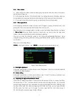
Click the button to select “Alarm”, then press the button to choose alarm on/off. Choose “ on” to

turn on the alarms and “ off” to turn off the alarms.

Figure 6 Alarm Setting Menu

c)

c)

c)

c)

Pulse

Pulse

Pulse

Pulse sound

sound

sound

sound indication

indication

indication

indication setting

setting

setting

setting

Click the button to select “Pulse Sound”, then press button to choose to have the Pulse Sound (heart

beat) “on” or “off”.

d)

d)

d)

d)

Exit

Exit

Exit

Exit the

the

the

the Alarm

Alarm

Alarm

Alarm setting

setting

setting

settingssss

Click button to select “EXIT”, then Press button to exit the Alarm Settings Menu.

C

C

C

C

ID

ID

ID

ID setting

setting

setting

setting

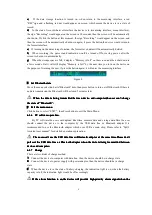
The user could set device ID by software "SpO

2

Assistant".The user could set character string

which could only be made of number or letter and not be beyond 7 bits

Figure 7 SpO2 Assistant program

IIIIffff the

the

the

the users

users

users

users choose

choose

choose

choose to

to

to

to turn

turn

turn

turn on

on

on

on the

the

the

the synchronizing

synchronizing

synchronizing

synchronizing display

display

display

display function

function

function

function on

on

on

on computer,

computer,

computer,

computer, it

it

it

it would

would

would

would

probably

probably

probably

probably take

take

take

take several

several

several

several seconds

seconds

seconds

seconds for

for

for

for the

the

the

the data

data

data

data to

to

to

to appear

appear

appear

appear on

on

on

on the

the

the

the computer

computer

computer

computer screen

screen

screen

screen

D

D

D

D

Data

Data

Data

Data storage

storage

storage

storage setting

setting

setting

setting

This device can record 24 hours data including pulse rate and SpO

2

value accurately and upload the

data to the computer for display and analysis.

a)

a)

a)

a)

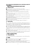
In the main menu interface,click button to move the selection bar to "Record" item,then press

button to enter the record beginning time setting dialog box as figure 8.

b)

b)

b)

b)

Click button to move the underline to the number that you want to set,then press button to set

time. After setting time,move the underline to "Y",then press button to exit the “time setting menu”,

and recording will begin.If move the underline to "N",then press button to cancel record,and the data

stored in memory will not be deleted.

Summary of Contents for CMS50EW

Page 1: ...I...

Page 2: ...sensor sensor sensor sensor should should should should not not not not be be be be applied applied applied applied to to to to the the the the same same same same finger finger finger finger for for...

Page 3: ...tions 4 4 1 Main performance 4 4 2 Main Parameters 4 5 Installation 5 5 1 View of the front panel 5 5 2 Installing the hanging rope 5 5 3 Accessories 5 6 Operating Guide 6 6 1 Application method 6 6 2...

Page 4: ...anyard is made of non sensitive material Please do not use lanyard if the user is allergic to lanyard Do not enwind neck with lanyard in order to avoid accident The disposal of scrap instrument and it...

Page 5: ...is used to adult or infant it depends on the probe selected optional The update period of data is less than 5 seconds which is changeable according to different individual pulse rate Please read the...

Page 6: ...peration of the product is simple and convenient B B B B The product is small in volume light in weight and convenient in carrying C C C C Low power consumption 2 2 2 2 2 2 2 2 Major Major Major Major...

Page 7: ...ore working abnormally which is due to low voltage E Automatically power off function when the device is under the state of measuring interface without external probe it will automatically power off w...

Page 8: ...rement DC 3 6 V 4 2V G G G G Optical Optical Optical Optical Sensor Sensor Sensor Sensor Red light wavelength is 660nm 6 65mW Infrared wavelength is 880nm 6 75mW H H H H Adjustable Adjustable Adjustab...

Page 9: ...side side side side If If If If the the the the alarm alarm alarm alarm function function function function is is is is on the on the on the on the device device device device will will will will prov...

Page 10: ...Bluetooth The specific operation methods are as follows Please note in the Settings Menu CLICK CLICK CLICK CLICK short push of button and PRESS PRESS PRESS PRESS prolonged push of power button 1sec Fi...

Page 11: ...he the Alarm Alarm Alarm Alarm setting setting setting settings s s s Click button to select EXIT then Press button to exit the Alarm Settings Menu C C C C ID ID ID ID setting setting setting setting...

Page 12: ...u Click button to select EXIT then Press button to exit the Main Menu 6 1 6 6 1 6 6 1 6 6 1 6 PC PC PC PC software software software software operation operation operation operation By PC software the...

Page 13: ...Please clean and disinfect the device after operating according to the User Manual 7 1 6 6 6 6 3 3 3 3 Clinical Clinical Clinical Clinical restrictions restrictions restrictions restrictions A A A A A...

Page 14: ...se Pulse Pulse Pulse Rate Rate Rate Rate are are are are not not not not display display display displayed ed ed ed stabl stabl stabl stably y y y 1 The finger is not laid inside deep enough 2 The fin...

Page 15: ...EE 2002 96 EC 10 10 10 10 Function Function Function Function Specification Specification Specification Specification Information Information Information Information Display Display Display Display Mo...

Page 16: ...ensity Range Continuous bar graph display the higher display indicate the stronger pulse Battery Battery Battery Battery Requirement Requirement Requirement Requirement Voltage 3 7 rechargeable lithiu...

Page 17: ...14 Appendix Appendix Appendix Appendix State Alarm condition delay Alarm signal generation delay Low voltage alarm 1s 20ms Spo2 alarm 330ms 20ms Pulse rate alarm 330ms 20ms Probe error alarm 16ms 20ms...

Reviews: