Intended use
The product is intended for mounting in a PCIe-slot on a computer, where it enables the use
of a mini PCIe card (short or long design). Through the 3 antenna connections, the product is
especially intended for use with mini PCIe WLAN or mini PCIe GSM cards.
This product complies with the applicable national and European regulations. All names of
companies and products are the trademarks of the respective owners. All rights reserved.
Contents
• Adapter card
• 3 antennas
• Fastenings for short mini PCIe cards
• Operating instructions
Safety Instructions
The warranty will be void in the event of damage caused by failure to observe
these safety instructions. We do not assume any liability for any resulting
damage.
We shall not accept liability for damage to property or personal injury caused
by incorrect handling or non-compliance with the safety instructions. In such
cases, the warranty will be null and void.
• The unauthorised conversion and/or modification of the product is not allowed
because of safety reasons.
• The product is not a toy and should be kept out of the reach of children.
• No part of the product may get damp or wet.
• Do not leave packaging material carelessly lying around, as it could become a
dangerous plaything for children.
• Handle the product with care; it can be damaged by impacts, blows, or accidental
falls, even from a low height.
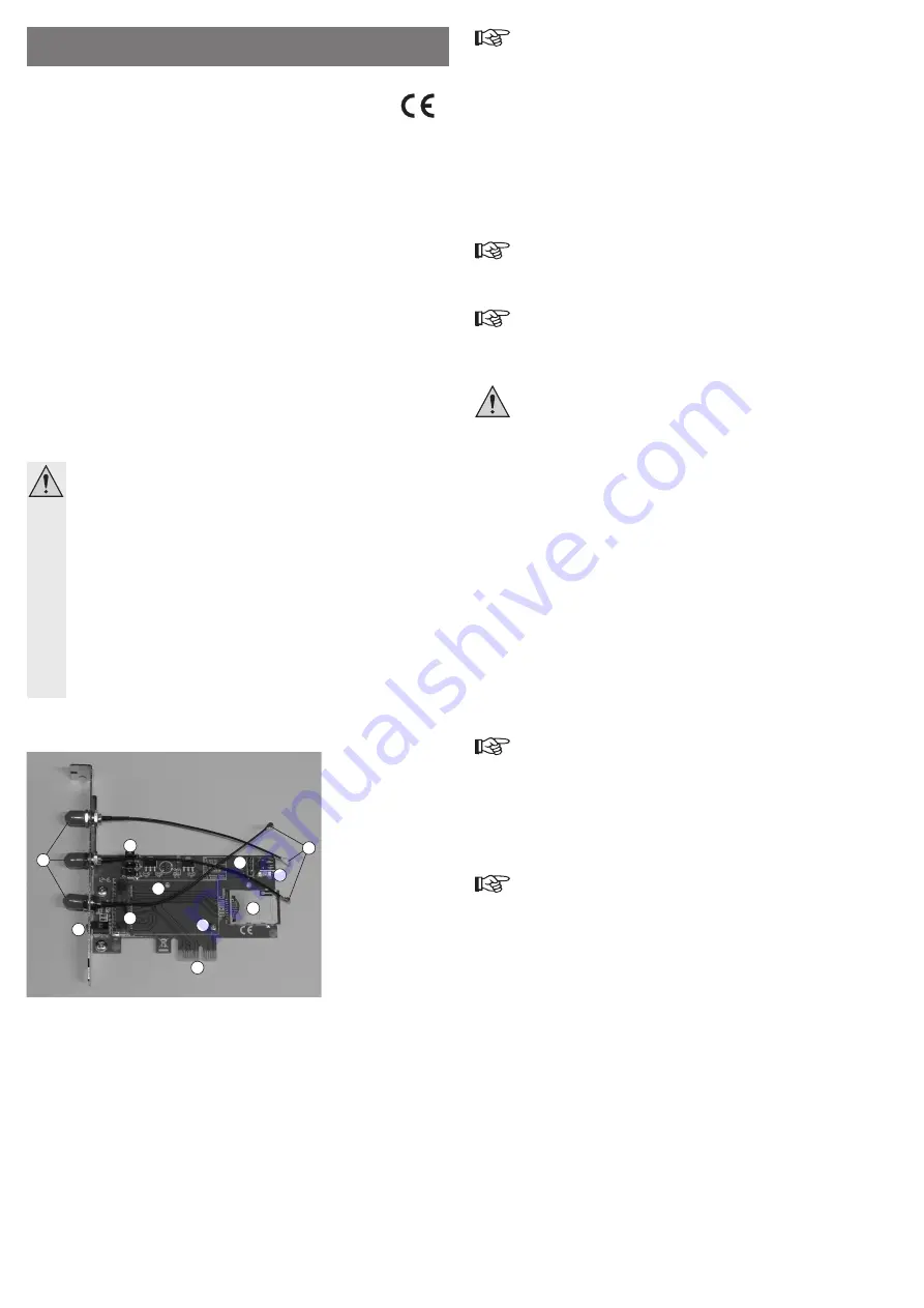
Connections and Control Elements
3
5
6
4
9
8
1
7
2
10
11
1 Connections for the provided antennae
2 LEDs
3 Contact strip for mini PCIe card
4 Jumpers for configuration
5 4-pin USB pin strip
6 USB port
7 Connector plug for WLAN/GSM
8 Slot for GSM card
9 PCIe connection
10 Mounting point for a long mini PCIe card
11 Mounting point for a short mini PCIe card
Important!
A mini PCIe card can work in two different ways - based on either USB or PCIe.
Unfortunately, the operating mode of the mini PCIe card cannot be specified right
away, unless the manufacturer has indicated this.
If the mini PCIe card that you want to plug into the adapter card is USB-based, then
a suitable USB cable that is available as an accessory is required (either a 4-pin
internal USB cable for connection to the motherboard or a suitable USB cable).
Otherwise, the operating system will not find any new hardware.
Depending on the design, many mini PCIe cards even require both connections
(PCIe and USB).
With the jumpers (4) JP1 and JP2, you can switch between power supply over PCIe (basic
setting, Pin 2-3 is connected) or USB (Pin 1-2 is connected).
Pin 1 of the jumpers is marked with a small arrow.
The jumper (4) JP3 can be used to switch the wireless function on (Pin 1-2 is connected) or off
(basic setting, Pin 2-3 is connected).
To use a WLAN or GSM mini PCIe card, the jumper JP3 must be placed in position
1-2. Pin 1 of the jumper is marked with a small arrow.
Installation
If you do not have the expertise to install the device correctly, please contact
an expert or a specialist workshop and let them carry out the installation!
Switch off the computer in which the mounting frame is to be installed as well
as all connected devices and separate all devices from the mains voltage; pull
the mains plug! Just turning off at the on/off switch is not enough!
• Open your computer’s housing and carefully remove the cover.
• The adapter card offers the option of operating a short or a long mini PCIe card. So that a
short mini PCIe card can be mounted, corresponding fastenings are included in the package
(spacer/screw).
The mounting point (11) should be used for a short mini-PCIe card, the mounting point (10)
for a long mini-PCIe card.
• Insert the mini PCIe card in the contact strip (3). Hold the mini PCIe card in a slightly slanted
position; slide it into the contact strip and fold it down. Then screw the mini PCIe card firmly
into place.
• A total of 3 antenna connections (7) are available for operating a WLAN or GSM mini PCIe
card. If the mini PCIe card you use has only one or two antenna connections (instead of
three), it does not matter which you use. Just make sure later on that the provided antennae
are attached to the right connection.
Carefully push the plug (7) onto the connections of your mini PCIe card. Do not use force.
• Adjust the jumpers JP1, JP2 and JP3 correctly; see chapter “Connections and controls”.
Normally, JP1 and JP2 can be left in the basic setting (Pins 2-3 are connected;
power supply occurs via PCIe). The jumper JP3 serves to switch the wireless func-
tion on and off. For a wireless PCIe card to be able to be used, this must of course
be activated (Pins 1-2 are connected).
For a USB-based mini PCIe card, move the two jumpers JP1 and JP2 (4) to the 1-2 position.
Pin 1 is marked with a small arrow.
Moreover, either the USB socket (6) or the USB pin strip (5) should be connected to a USB
port on the computer using a suitable USB cable (not included, available separately).
You will find a label for the pin assignment (GND, D+, D- and +5V) next to the pin
strip J1 (5). When connecting, pay attention to the correct arrangement of the con-
nector (GND = black cable, +5V = red cable); otherwise not only the motherboard,
but also the adapter card and the inserted mini PCIe card will be destroyed. Loss of
warranty!
For a PCIe-based mini PCIe card, move the two jumpers JP1 and JP2 (4) to the 2-3 position
(Pin 1 is marked with a small arrow).
G
O P E R AT I N G I N S T R U C T I O N S www.conrad.com
PCI-Express to Mini-PCI-
Express Adapter
Item no. 1040386
Version 01/14