Connects2 Aerpro APVPO11 Manual Download Page 9

www.

aerpro

.com

www.connects2.com

9

INSTALLATION

Alternatively coding and decoding of rear-view camera and ParkAssistant 

(e.g. if steering-wheel buttons not existing, only PCM3.1)

Alternatively to coding through the steering-wheel buttons, the coding and 

decoding of rear-view camera and Park Assistant can be completed via the 

loose white cable in connection with Dip 3 and 4 on the Interface.

Dip 

Function

ON

OFF

Dip 3  Rear-view camera 

Coding 

Decoding

Dip 

ParkAssistant

Coding

Decoding

1.

Turn on ignition

2.

Wait until the head-unit has booted up

3.

Set Dip3 and Dip4 of Interface (depending on the desired coding/

decoding)

4.

Put +12V for 5 sec. to the white cable

5.

During configuration the red and blue LED will flash

inside the CAN-box (visible at the male 8pin Molex connector).

The PCM will reset after 5-10 seconds
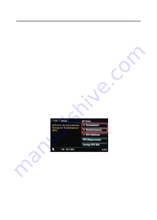
6.

The red and the blue LED inside the Interface will light up and the

notice “Rear-view camera“ or “ParkAssistant” will appear in the

menu after successful coding (or disappear after successful

decoding)

If a factory PDC exists in the car, set Dip4 to “ON” while coding, otherwise the 

factory PDC will be decoded

Summary of Contents for Aerpro APVPO11

Page 1: ...APVPO11 Rear View Camera Input and Video In Motion www connects2 com...

Page 2: ...tion Technical knowledge is necessary for installa tion The place of installation must be free of moisture and away from heat sources Please ensure you use the correct tools to avoid damage to the veh...

Page 3: ...ON PCM 3 1 with video in motion deactivated OFF ON OFF OFF OFF ON Interface Dipswitch Functions Dip 1 Activation of Video in Motion Dip 2 Existing Rear View Camera Dip 3 Coding rear view camera by wh...

Page 4: ...4 CAN HIGH connection to the head unit Blue Pin 3 CAN LOW connection to the head unit Yellow Black Pin 8 CAN HIGH connection to the vehicle Blue Black Pin 7 CAN LOW connection to the vehicle Red Pin 1...

Page 5: ...face Harness and Factory Navigation Monitor 1 Connect the female 8pin Molex connector of the harness to the male 8pin Molex connector of the Interface 2 Transfer the female Quadlock connector of the v...

Page 6: ...s 2 Connect the green cable of the harness to the camera power supply 12V max 400mA The green cable is high when reverse gear is engaged and if ignition is off The power will be deactivated from a spe...

Page 7: ...g configuration the red and blue LED will flash inside the CAN box visible at the male 8pin Molex connector The PCM will reset after 5 10 seconds 6 Disengage both steering wheel buttons 7 When coding...

Page 8: ...ed and the blue LED inside the CAN Box will light up and the notice Park Assistant will appear in the menu Decoding of the Park Assistant only PCM3 1 It is possible to decode the Park Assistant as fol...

Page 9: ...t Coding Decoding 1 Turn on ignition 2 Wait until the head unit has booted up 3 Set Dip3 and Dip4 of Interface depending on the desired coding decoding 4 Put 12V for 5 sec to the white cable 5 During...

Page 10: ...Interface depending on the desired coding decoding 4 Put 12V for 5 sec to the white cable 5 During configuration the red and blue LED will flash inside the CAN box visible at the male 8pin Molex conn...

Page 11: ...www aerpro com 11 NOTES...

Page 12: ...www aerpro com 12 NOTES...

Reviews: