


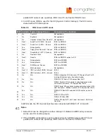

Table 19
COM Signal Descriptions
Signal
Description of COM signals
I/O
PU/PD
Comment
DTR1#
Data terminal ready for COM1
O 5V
PU 4k7 5V
DTR1# is a boot strap
signal (see note below)
DTR2#
Data terminal ready for COM2
O 5V
PD 100k 5V
RI1#, RI2#
Ring indicator for COM1/COM2
I 5V
PD 100k 5V
TXD1, TXD2
Data transmit for COM1/COM2
O 5V
PU 4k7 5V
TXD1 and TXD2 are boot
strap signals (see note
below)
RXD1, RXD2
Data receive for COM1/COM2
I 5V
PD 100k 5V
CTS1#, CTS2#
Clear to send for COM1/COM2
I 5V
PD 100k 5V
RTS1#
Request to send for COM1
O 5V
PD 4k7
RTS1# is a boot strap
signal (see note below)
RTS2#
Request to send for COM2
O 5V
PD 100k 5V
DCD1#, DCD2#
Data carrier detect for COM1/COM2
I 5V
PD 100k 5V
DSR1#, DSR2#
Data set ready for COM1/COM2
I 5V
PD 100k 5V
Note
Some signals have special functionality during the reset process. They may bootstrap
some basic important functions of the module. For more information refer to section 7.9
of this user's guide.
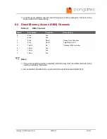
Table 20
Keyboard and Infrared Signal Descriptions
Signal
Description of keyboard
and infrared signals
I/O
PU/PD
Comment
KBDAT
Keyboard Data
I/O 5V
PU 8k2 5V
KBCLK
Keyboard Clock
O 5V
PU 8k2 5V
MSDAT
Mouse Data
I/O 5V
PU 8k2 5V
MSCLK
Mouse Clock
O 5V
PU 8k2 5V
IRTX
Infrared Transmit
O 5V
IRRX
Infrared Receive
I 5V
Copyright © 2006 congatec AG
X945m13
54/102


