


Copyright
©
2019
congatec
AG
JCWLm10
45/55
8
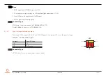
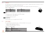
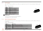
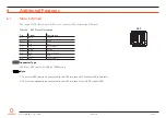
PM_SLP_S5#/GPIO_14
Soft-off state/General Purpose Input Output 14
9
WDG_EVENT/GPIO_15
Watchdog event/General Purpose Input Output 15
10
+ 3.3 V
3.3 V supply (standby)
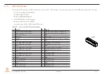
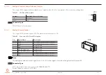
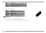
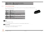
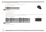
5.11
I²C Bus/SM Bus Header
The conga-JC370 provides header X7 for I²C/SM bus signals. The 3.3 V is provided through a 500 mA resetable fuse.
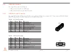
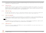
Table 33 X7 Pinout Description
Pin Signal
Description
1
PM_THRM#
Thermal event from external sensor (should be driven by open
drain/collector output)
2
I2C_DAT
I2C data
3
GND
Ground reference
4
I2C_CLK
I2C clock output
5
+3.3 V
+3.3 V (standby) power output with 500 mA fuse
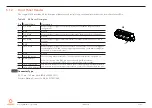
6
SMB0_ALERT# SMBus Alert signal from external device (should be driven by open
drain/collector output)
7
SMB0_DAT
SMBus data
8
GND
Ground reference
9
SMB0_CLK
SMBus clock output
10
+ 3.3 V
+3.3 V power output with 500 mA (active in deep sleep)
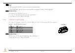
Note
1. All signals have 3.3 V level
2. Pin 5 is recommended for I2C devices while pin 10 is recommended for SMBus devices
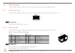
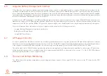
Connector Type
X7: 10-pin, 1.25 mm pitch picoblade header (Molex 0533981071)
Possible Mating Connector: Molex 0510211000
X7


