background image


Safe Operating Practices 


Important Safety Instructions 


Electrical Requirement 

1.


This puller should be grounded while in use to protect the operator from electric shock 
The power pack is equipped with a  3-conductor cord and 3-prong grounding type plug to 
fit the proper grounding type receptacle. The green conductor in the cord is the grounding 
wire. Never connect the green wire to a live terminal. If necessary, an adapter is available 
for connecting 3-prong plugs to 2-prong receptacles. The adapter’s green-colored lug 
must be connected to a permanent ground, such as a properly grounded outlet box. 


Extension Cords 

2.


Use only 3-wire extension cords that have 3-prong grounding-type plugs and 3-pole 
receptacles that accept the pullers plug.  


Outdoor Use Extension Cords 

3.


If used outdoors, the extension cord must be marked with the suffix W-A following the 
cord type designation (e.g., STJW-A). 


4.


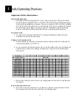
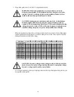
Use an extension cord with the proper wire size for the length of the cord. An undersized 
cord will cause a drop in line voltage, resulting in loss of power and overheating (See 
Chart below). 


5.


Position the cord that it will be clear of any rotating parts and will not be a trip hazard to 
the operator.  


Don’t Abuse Electrical Cord 

6.


Never lift or carry the puller by the cord, and never yank the cord to disconnect it from 
the receptacle. Keep the cord away from heat, oil, and sharp edges 

Total Amps

0-2.0

2.1-3.4

3.5-5.0

5.1-7.0

7.1-12.0

12.1-16.0

16.1-20.0

Ext. Cord Length

Wire Size

25 ft.(8 m)

18

18

18

18

16

14

12

50 ft. (15 m)

18

18

18

16

14

12

10

75 ft. (23 m)

18

18

16

14

12

10

8

100 ft. (30 m)

18

16

14

12

10

8

8

150 ft. (46 m)

16

14

12

12

8

8

6

200 ft. (61 m)

16

14

12

10

8

6

4

300 ft. (91 m)

14

12

10

8

6

4

4

400 ft. (122 m)

12

10

8

6

4

4

2

500 ft. (152 m)

12

10

8

6

4

2

2

600 ft. (183 m)

10

8

6

4

2

2

1

800 ft. (244 m)

10

8

6

4

2

1

0

1000 ft. (305 m)

8

6

4

2

1

0

0

Summary of Contents for CableGlider LW

Page 1: ...USER S GUIDE SAFETY MANUAL CableGlider LW Cable Puller...

Page 2: ...2...

Page 3: ...jefe Save this user s guide for future reference If you have questions on Safety Operations Applications Call 1 800 533 2077 WARNING Electrical equipment is hazardous Train personnel to use basic safe...

Page 4: ...perating Practices 6 Puller Assembly Instructions 10 Operating Instructions 12 Appendices 14 LW Cableglider Assembly 14 LW Cableglider Wiring Diagram 16 LW Cableglider Accessories 17 LW Cableglider Ac...

Page 5: ...s A Operator must know the required safety directives to run the product that are pertinent to the country where it is being used B Operator in charge of the product and installation project must be a...

Page 6: ...e marked with the suffix W A following the cord type designation e g STJW A 4 Use an extension cord with the proper wire size for the length of the cord An undersized cord will cause a drop in line vo...

Page 7: ...y contact with grounded surfaces e g metal pipes Keep Children Away 14 Do not let anyone but the operator touch the puller or the extension cord all visitors should be kept a safe distance away from t...

Page 8: ...Check for proper alignment of moving parts and that there is no binding Ensure all mounting hardware is securely fastened Any damaged part should be properly repaired or replaced by an authorized serv...

Page 9: ...nificant loss of strength in a short time Discoloration is the key 2 DIRT GRIT Using the rope in mud sand or dirt will allow particles into the construction causing the strength of the rope to deterio...

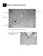
Page 10: ...embly Instructions 1 Remove puller components from the carrying case 2 Place Power Unit into the Base Plate and secure with Clevis Pin See Figure 1 Figure 1 Sheave Extension Power Unit Square Extensio...

Page 11: ...re 2 4 Slide Sheave Extension into Square Adapter Reinstall Lock Pin See Figure 3 Sheave Extension can be adjusted to desired height during puller set up Figure 3 5 Remove Hitch Pin from Extension Hea...

Page 12: ...s WARNING Inferior rope may break Ensure the rope is rated for the load Failure to do so could result in serious personnel injury or death 5 Manually tension the pull line and wrap it counter clockwis...

Page 13: ...xcessive heat sharp edges and the puller itself and keep the cord out of damp or wet areas Also repair or replace damaged extension cords before using Total Amps 0 2 0 2 1 3 4 3 5 5 0 5 1 7 0 7 1 12 0...

Page 14: ...14 Appendices LW CableGlider Assembly 5...

Page 15: ...VIS 0 625 X 3 50 1 14 02289411 LOCKWSHR 0 31 REGULAR ST CZ 8 16 08678205 FORK RETAINING 3000 CG 1 17 08678208 EXTENSION SHEAVE WELD 3000 CG 1 18 08678211 TUBE FRONT WELDMENT 1 19 08678215 MOUNT FRONT...

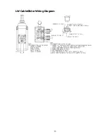
Page 16: ...16 LW CableGlider Wiring Diagram...

Page 17: ...260 External Adapter 2 50 Conduit 08678265 External Adapter 3 00 Conduit 08678270 External Adapter 3 50 Conduit 08678275 External Adapter 4 00 Conduit 08678276 Internal Adapter 1 00 Conduit 08678277 I...

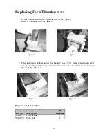
Page 18: ...e lockwasher on thumbscrew See Figure 9 use a 5 16 socket to push lockwasher onto the thumbscrew See Figure 10 Thumbscrew needs to be pushed till it is resting on the inside lip of the fork Replacemen...

Page 19: ...19 NOTES...

Page 20: ...20 NOTES...

Page 21: ...21 NOTES...

Page 22: ...d the original manufactures written instructions Condux s sole liability and the purchaser s sole remedy for a failure of goods under this limited warranty and for any and all claims arising out of th...

Reviews: