50
Mounting and installation work
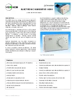
5.8.4 Installation work external connections
Connecting the external safety chain
B3
B2
B1
K2
24VAC External Safety Loop Control signal (GND) Control signal (IN) Limit signal (IN) Control signal (V+) Limit signal (GND) Safety circuit BP Safety circuit BP
1 2 3 4 5 6 7 8 9
XE2
J3
Control compartment
Do not apply extrane-
ous voltage via K1!
The potential-free contacts of external moni t or ing de-
vices (e.g. ventilation interlock, safety high limit humidis-
tat, airflow monitor, etc.) are connected in series (safety
chain "K2") to the terminals "1" and "2" of the control
terminal block "XE2" inside the control compartment in
accordance with the wiring diagram.
The connecting cable must be led through a cable gland
into the control compartment.
Caution!
A
high limit humidistat is highly recomen-
ded
to prevent risk of over-humidification and potential
damage to property.
Note:
If, for whatever reason, no external monitor-
ing devices are connected, a jumper wire "J3" must
be installed on the contacts "1" and "2" of the control
terminal block.
CAUTION! Do not apply any extraneous voltage to
contacts "1" and "2" via the contacts of the external
monitoring devices.
Connecting the demand or humidity signal
JP2
JP1
+ –
Y
A1
GND (3)
IN (4)
24VAC External Safety Loop Control signal (GND) Control signal (IN) Limit signal (IN) Control signal (V+) Limit signal (GND) Safety circuit BP Safety circuit BP
1 2 3 4 5 6 7 8 9
XE2
Control compartment
The signal cable of an external controller or of a humidity
sensor (if the internal P/PI controller is used) are to be
connected according to the wiring diagram to the termi-
nals "3" (GND) and "4" (IN) of the control terminal block
"XE2" inside the control compartment. The admissible
signal values can be found in the technical data table
in the operation manual. The connecting cable must be
led through a cable gland into the control compartment.
Note: The admissible humidity control signal values
can be found in the technical data table in the opera-
tion manual.
If a shielded signal cable is used, connect the shielding
to terminal "3" (GND).
Caution!
If the shielding of the control signal is
already
connected to a po ten tial or a grounded conductor,
do not
connect it to terminal "3" (GND).