background image


3.4.


Browsing Video 

Users can view real-time video in the web management system. 

3.4.1.


Preparation 

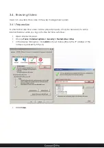
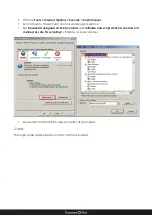
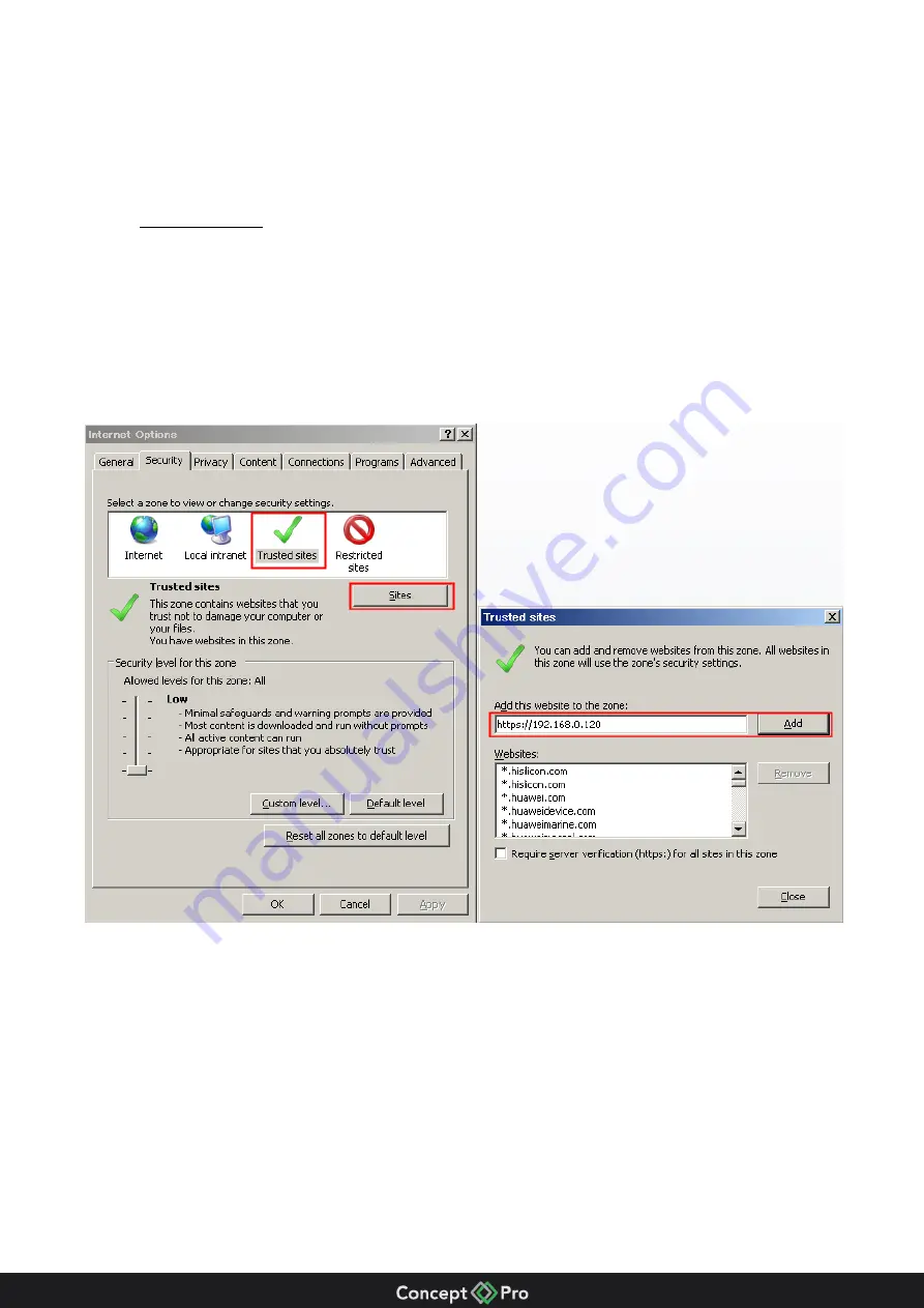
To ensure that real-time video can be played properly, it may be necessary to set up 
Internet Explorer when you log on for the first time as follows: 


Open Internet Explorer.   


Choose

 Tools > Internet options > Security > Trusted sites > Sites


In the display dialog box, click

 Add

 as shown below (Ensure the IP address of the 

camera is prefixed by https://). 


Click 

Close


Summary of Contents for VHSDIR-670EXT-IP

Page 1: ...VHSDIR 670EXT IP IP HIGH SPEED DOME IP SURVEILLANCE USER MANUAL ...

Page 2: ...ectric shock keep power plugs dry and clean Strictly observe installation requirements The manufacturer shall not be held responsible for damage to the device caused by users non conformance to these requirements Strictly conform to local electrical safety standards and use power adapters that are marked with the LPS standard Use accessories delivered with this device The voltage must meet input v...

Page 3: ...ric heaters and other heating equipment Keep the device away from moisture dust extremes of heat and cold and strong electromagnetic radiation and electric fields If the device is installed outdoors take insect and moisture proofing measures Remove the power plug if the device is idle for a long time Before unpacking check whether the warranty seal is damaged If it is contact customer services or ...

Page 4: ...on 14 3 1 Login and Logout 14 3 1 1 Logging in to system 14 3 1 2 Logging out 14 3 2 Live Video page layout 15 3 2 1 PTZ Control Box 17 3 2 2 Module Control Box 18 3 2 3 Warnings 18 3 3 Configuration page layout 19 3 4 Browsing Video 20 3 4 1 Preparation 20 3 4 2 Downloading the right control 22 3 4 3 No video display 22 3 4 4 Real time video in Chrome Firefox and Safari 22 3 5 Setting Local Netwo...

Page 5: ... 1 Device Description 1 1 Product Appearance Fig 1 Appearance of the IR Network High Speed Dome Fig 2 Multi head cable from dome camera ...

Page 6: ...el 2 Red Black Alarm output channel 2 common terminal Orange Alarm input channel 1 Orange Black Alarm input channel 2 Yellow Alarm input channel 3 Yellow Black Alarm input channel 4 Green Alarm input channel 5 Green Black Alarm input channel 6 Blue Alarm input channel 7 Blue Black Alarm input channel common terminal 2 N A Network port Connects to a standard Ethernet network 3 Red taped core Audio ...

Page 7: ... core Audio input Receives analog audio signals from devices such as a sound pickup device 5 Red core AC 24V power supply wire The red and black core supply power for the device and supply power for the heater Black core 6 N A Grounding wire N A ...

Page 8: ...eters for the main stream and sub stream be configured separately Supports dynamic stream parameters based on different image quality requirement Supports independent hardware compression and constant bit rate CBR and variable bit rate VBR Videos can be compressed using the Motion Joint Photographic Experts Group MJPEG or H 264 standards The frame rate and image quality can be configured 1 2 3 I O...

Page 9: ...allation 2 1 Tools required for installation Tool Description Phillips screwdriver Claw hammer Hammer drill Level Slotted screwdriver included with camera Screws included with camera Hexagon wrench included with camera ...

Page 10: ...e camera ensure that the multi head cable is not exposed Fig 3 Camera Dimensions mm 2 3 Wall Mounted installation Mark out drilling points on wall based on bracket size Drill four φ8mm holes to minimum 60mm depth Insert the expansion bolts into the holes Fix the connector to the bracket as shown in Fig 4 Fig 4 ...

Page 11: ...wn in Fig 5 Fig 5 Attach the PTZ camera to the wall bracket component and fit it into the connector Tighten the four screws to fix the connector and camera as shown in Fig 6 Fig 6 Mount the PTZ dome camera to the wall and fully tighten the four screws on the bracket ...

Page 12: ...nsion bracket Drill four φ8mm holes to minimum 60mm depth Insert the expansion bolts into the holes Fix the connector to the suspension bracket base as shown in Fig 7 Fig 7 Thread all cables through the hole on the side of the suspension bracket as shown in Fig 8 Fig 8 ...

Page 13: ...spension bracket component and fit it into the connector Tighten the four screws to fix the camera and bracket as shown in Fig 9 Fig 9 Mount the PTZ dome camera to the mounting surface and fully tighten the four screws on the bracket ...

Page 14: ...ss Enter The login page is displayed as shown Input the User Name and password The default name is admin The default password is admin Change the password when you log in the system for first time for security You can change the system display language on the login page Click Login The live video page is displayed 3 1 2 Logging out Click Sign out in the upper right corner of the main page The logi...

Page 15: ...e displayed in this area You can also set sensor parameters 2 Tabs Use to switch between Live Video and Configuration pages 3 Logout password area Buttons to change password and to return to login page 4 Control area Supported options to Select Video Stream Open PTZ Control box Switch between live and recorded video Open Module Control box ...

Page 16: ... ...

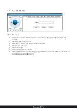
Page 17: ...the focal length and aperture Adjust the PTZ rotation speed Add delete and invoke the presents and tacks Set up scans and tours Adjust IR settings Set the direction to due north Set the PTZ timer for scheduled triggering of presets and tracks This uses the time set in camera so ensure it is correct ...

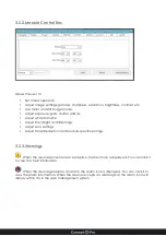
Page 18: ...Night and IR settings Adjust Lens settings Adjust Noise Reduction and module specific settings 3 2 3 Warnings When the device encounters an exception the fault icon is displayed You can click it to view the fault information When the device generates an alarm the alarm icon is displayed You can click it to view the alarm information When the device accepts an alarm signal the alarm icon will displ...

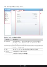
Page 19: ...including the device information audio and video streams alarm setting and privacy mask function 2 Detail area This changes to show information and allow entry of settings for the item selected in the Menu area 3 Tabs Use to switch between Live Video and Configuration pages 4 Logout password area Click button to change password Click button to return to login page ...

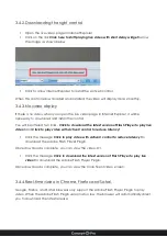
Page 20: ...video can be played properly it may be necessary to set up Internet Explorer when you log on for the first time as follows Open Internet Explorer Choose Tools Internet options Security Trusted sites Sites In the display dialog box click Add as shown below Ensure the IP address of the camera is prefixed by https Click Close ...

Page 21: ...eX controls and plug ins section Set Download unsigned ActiveX controls and Initialize and script ActiveX controls not marked as safe for scripting to Enable as shown below Download and install the player control as prompted The login page is displayed once the control is loaded ...

Page 22: ...he latest version of Flash Player to play live video and Click to play video with ActiveX control to reduce latency Click the message Click to play video with ActiveX control to reduce latency to download the Adobe Flash Player Plugin Once download is complete you can view the video Or Click the message Click to download the latest version of Flash Player to play live video to download the Adobe F...

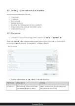
Page 23: ...ure In the Menu area of the Configuration tab Choose Device Local Network The Local Network page is displayed as shown below If DHCP is turned on the central portion is collapsed and only the assigned IP address is shown Set the parameters as described in the table below Parameter Description Setting IP Protocol IPv4 is the IP protocol that uses an address length of 32 bits Select a value from the...

Page 24: ...Name Server Enter a value manually Default value 192 168 0 1 Alternate DNS Server IP address of a Domain Name Server to use if the preferred DNS server is down Enter a value manually Default value 192 168 0 2 MTU Set the maximum value of network transmission data packets Enter a value manually Range 800 1500 default value 1380 Note please do not change it arbitrarily Click OK If the message Networ...

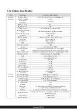
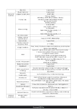
Page 25: ...amp Exposure mode AUTO Manual Shutter Priority Iris Priority Bright Priority Electric shutter Auto Manual 1 10000 1 50s Gain Auto Manual 0 15 Iris Auto Manual 0 13 Slow shutter ON OFF Sharpness 0 100 Contrast 0 100 Saturation 0 100 Light suppression Support Defogging ON OFF Nose reduction Manual Auto S N ratio 50dB Dome function Horizontal range 360 Degree continuous Horizontal speed 0 01 180 degr...

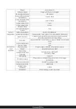
Page 26: ...3 Support 32 Chinese and English characters 1920 1080 SBC case 48 48 DBC case 24 48 VGA SBC case 16 16 DBC case 16 8 Audio compression G 711 64kbps RAW_PCM 128kbps Bidirectional talk Supported Heartbeat Supported Alarm events and handing Internal dynamic external input or planned trigger events Automatic image upload on alarm over Email and HTTPS Network transmission Auto adaptive flow control tec...

Page 27: ...interface Alarm function 7 alarm input switch type 2 alarm output support normally open and normally close SD card One MICRO SD card interface support 32GB MicroSD HC card Motion detection Yes Privacy mask N A Environme ntal features Power supply Power supply AC24V 2 5A heater power Power Maximum power 40W Operating temperature and humidity Temperature 40 60 Humidity 90 Defogging Support Protectio...

Page 28: ...ace Normal self check but out of control RS485 bus bad connection Check the RS485 connection Dome ID setup is wrong Reselect Protocol setup is wrong Reset and Restart Vague image Bad connection of the video Reseat connector Power supply inadequate Replace Dome camera out of control Self check error Restart Bad connection of controller Reseat connector Bad control of matrix Restart Lens out of cont...

Page 29: ... ...

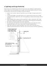
Page 30: ...nes such as a high voltage transformer substation extra strong lightning protection equipment must be installed Ensure lightning and surge protection equipment outdoor equipment and cable layouts are designed and installed in accordance with all appropriate regulations The system must be grounded with equal potentials The earth ground connection must satisfy anti interference and electrical safety...

Page 31: ...ces Indicates that the concentration of the hazardous substance contained in all the homogeneous materials of this part is below the limit requirement of the SJ T 11363 2006 standard Indicates that the concentration of the hazardous substance contained in all the homogeneous materials of this part is above the limit requirement 101 500 0137 01 ...

Reviews: