


CRS-280/280L IF Switch for 1:N Redundancy
Revision -
Appendix A
A-1
MN-CRS-280/280L
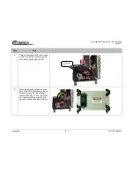
Appendix A. CABLE DRAWINGS
A.1 Introduction
This appendix contains drawings of cables used with the CRS-280 (70/140 MHz) and the CRS-280L (L-Band) IF Switch for 1:N
Redundancy. These cables are broken into two categories – Control Interface Cables and IF Interface Cables:
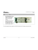
•
The Control Interface Cables are used to connect the CRS-280L rear panel J1 CRS Control Interface or J2 SMS Control
Interface connector to its companion redundancy switch IF Switch Control Interface connector.
•
The IF Interface Cables may be selected and used to connect the CRS-280L, via the front panel Tx/Rx Type ‘N’
threaded female connectors, to the Redundant Modem and up to 10 traffic modems that are part of the 1:N redundancy
setup, as well as to any external uplink / downlink RF equipment.
Each section provides illustrations of the cables’ technical specifications; additionally, the table in each section cross-reference
to the illustrations found in
Chapter 4. CABLES AND CONNECTIONS
.
Summary of Contents for CRS-280
Page 28: ...CRS 280 280L IF Switch for 1 N Redundancy Revision Introduction 1 14 MN CRS 280 280L Notes ...
Page 68: ...CRS 280 280L IF Switch for 1 N Redundancy Revision Appendix B B 8 MN CRS 280 280L BLANK PAGE ...
Page 69: ......
Page 70: ...2114 WEST 7TH STREET TEMPE ARIZONA 85281 USA 480 333 2200 PHONE 480 333 2161 FAX ...