


CRS-280/280L IF Switch for 1:N Redundancy
Revision -
Redundancy System Configuration / Operation
5–1
MN-CRS-280/280L
Chapter 5. REDUNDANCY SYSTEM
CONFIGURATION / OPERATION
5.1
Overview
In order to avoid damage to the modems, the companion redundant switch, and
the CRS-280L L-Band IF Switch, and it is important for the user to follow this
sequence of configuration:
•
First,
connect cables between the (powered OFF) modems, companion
redundancy switch, and CRS-280L as outlined previously in Chapter 4.
CABLES AND CONNECTIONS.
•
Second,
configure the modems for 1:N redundant operation, as outlined in
the respective modem and companion switch Installation and Operation
Manuals.
•
Third,
once the modems have been properly configured for 1:N redundant
operations, the user should follow the instructions in the next two chapter
sections in the sequence they are presented.
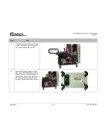
5.2
CRS-280L Input Power Cord Connections
Do not turn the CRS-280L power supply switches to the
on
position until all
system connections are in place.
Connect the AC power cords as follows:
Step
Instructions
1
Ensure that both power supply switches are in the off position before connecting the power supply
power cords.
2
Each CRS-280L is supplied with two power cords – one for each power supply power input.
Connect the female end of each supplied power cords to its mating socket.
3
Plug both power cords into the AC power source.
Summary of Contents for CRS-280
Page 28: ...CRS 280 280L IF Switch for 1 N Redundancy Revision Introduction 1 14 MN CRS 280 280L Notes ...
Page 68: ...CRS 280 280L IF Switch for 1 N Redundancy Revision Appendix B B 8 MN CRS 280 280L BLANK PAGE ...
Page 69: ......
Page 70: ...2114 WEST 7TH STREET TEMPE ARIZONA 85281 USA 480 333 2200 PHONE 480 333 2161 FAX ...