MENU - CAMERA (continued)
TP4MD/CD / TP10MD/CD / TP16MD/CD
9
E
N
G
L
IS
H
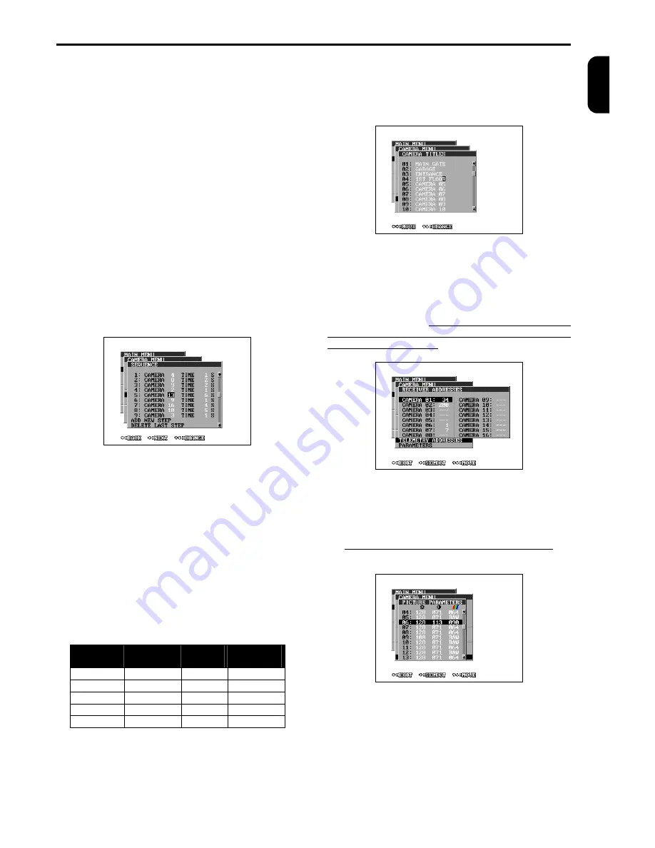
SEQUENCE
The menu SEQUENCE programmes the order and
time of the displaying (switching) of particular cameras
on analogue switching output (MON SPOT) or in LIVE
mode on main monitor. You can program from 2 up to
32 switching steps of the sequence. The individual
steps are marked with sequential numbers and are
arranged one under the other. If you want to choose
the camera or time of some step, you have to choose
the particular step with the help of direction keys up
and down at first. Then press the button
®
(CHOOSE) and now you can change the camera
number with the help of arrow keys. By another press-
ing the button (NEXT) you can go to edit the time. The
time of this step can be set up in the interval from 1 up
to 255 seconds. The next press of the button
®
fi-
nishes the editing of the chosen step. The last two
steps of the menu obtain the functions for the change
of the sequence length: adding a new step (ADD
NEW STEP) and deleting the last sequence step
(DELETE LAST STEP). By pressing the button
¬
(END) you can stop the editing of the sequence and
return to the camera menu.
TIME MULTIPLIER
If you would like to change the camera switching time,
it is not always necessary to reprogram the switching
sequence. All the time data of the sequence are mul-
tiplied with the parameter TIME MULTIPLIER
.
The
time of the displaying of particular cameras can be
quite lengthened or shortened and the proportion of
displaying particular steps (cameras) still lasts. It is
important to note that the time of displaying one step
after the change will still stay in interval of 1 to 255
seconds.
There is an illustrated example in the table, how the
switching time changes according to the programmed
switching sequence “Sequence time”, if you use the
time multiplier 8× or 1/4×.
CAMERA TITLES
Each camera can have its own title for better identifi-
cation. The title can include up to 16 symbols and
there can be used letters from A to Z, numerals from
0 to 9, symbols . , : ! ? ‘ + - * / ( ) < > = and a space.
TELEMETRY ADDRESSES
The address of the telemetry receiver can be defined
in the interval from 0 up to 255 for controlling the
PAN/TILT camera heads and lenses for each camera.
The multiplexer, with the help of this address, distin-
guishes particular devices, which are connected to the
RS 485 or CAN bus. If a camera does not have the
receiver address set up, you can not switch on the
telemetry for the camera.
PICTURE PARAMETERS
Colour multiplexers enable setting of picture parame-
ters for every camera. Implicit values are: 110 for
brightness, 64 for contrast, and 64 for colour. You are
not allowed to set colours if using B&W multiplex-
ers.
Using a B&W camera set colour to “B&W”.
The
camera displaying will be sped up.
Camera
Time of
sequence
Multiple
8 ×
Multiple
1/4
2
1 s
8 s
1 s
4
12 s
96 s
3 s
8
100 s
255 s
25 s
3
4 s
32 s
1 s
5
24 s
192 s
6 s
Summary of Contents for TP10CD
Page 2: ......


