P M 13 7 9
1
SECTION 1 SAFETY SIGNALS AND WORDS
IMPORTANT:
Statements identify special instructions necessary for the most efficient
operation of this equipment.
WARNING
WARNING statements identify procedures or practices which must be followed to
avoid seriuos personal injury or loss of life.
CAUTION
CAUTION statements identify procedures or practices which must be followed to
avoid minor personal injury or damage to this equipment.
The following safety alert symbol and signal words are used throughout this manual to call attention to and
identify different levels of hazard and special instructions.
SECTION 2 SPECIFICATIONS
Rated Weld Amperage
Duty Cycle
Wire Diameter
Length
Cooling System
250 Amperes
60 % With CO
2
.035" to .045" ( 0.89 to 1.14 mm)
10 ft. (3 m.)
Air
RECOMMENDED GUN
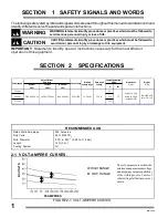
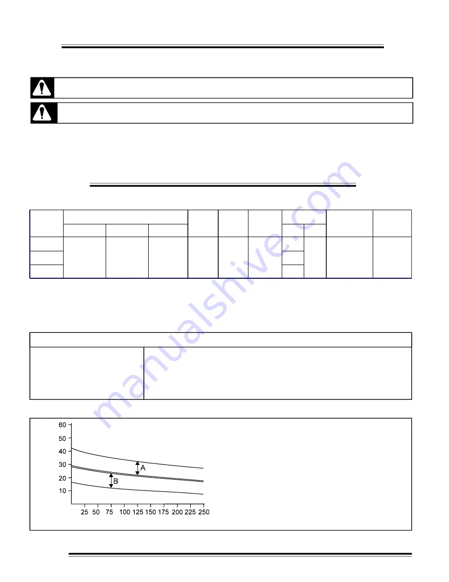
FIGURE 2-1 VOLT-AMPERE CURVES.
2-1 VOLT-AMPERE CURVES.
The volt-ampere curves show the
minimum and maximum voltage
and amperage output capabilities
of the welding source. Curves of
other settings fall between curves
shown.
A= HIGH RANGE
B= LOW RANGE
DC AMPERES
D
C
VO
L
T
S
Nominal
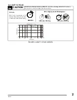
60%
Continue
100 %
Maximum
40 %
A
kW
230 V ac
43
460 V ac
21.5
575 V ac
17.2
Power supply
Open circuit
voltage
Input at Rated load,
60 Hz
Output Current
Duty cycle
Welding
voltage range
Current range
Weight
lb (kg)
250 A @ 26.5 V dc
190 A @ 23.5 V dc
300 A @ 28 V dc
30 A - 300 A
Dimensions
in (mm)
10 - 28 V dc
32 V dc
7.7
Heigh: 31.2 (794)
Width: 14.2 (362)
Length: 38 (965)
Net: 264.5 (120)
Ship.: 271 (123)

