P M 13 7 9
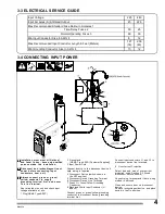
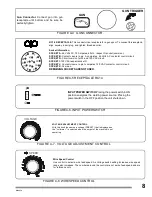
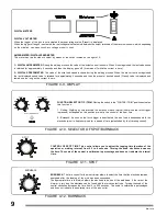
FIGURE 4-6. INPUT POWER SWITCH
8
VOLTAGE ADJUSTMENT CONTROL.
W ith this knob the same arc voltage (PRESET) that is displayed on
the '' voltmeter '' is selected when the output of the machine is not
operating
FIGURE 4-7. VOLTAGE ADJUSTMENT CONTROL
FIGURE 4-8 WIRE SPEED CONTROL
Wire Speed Control
Use control to select a wire feed speed. As Voltage switch setting increases, wire speed
range also increases. The numbers around the control are not a wire feed speed and are
for reference only
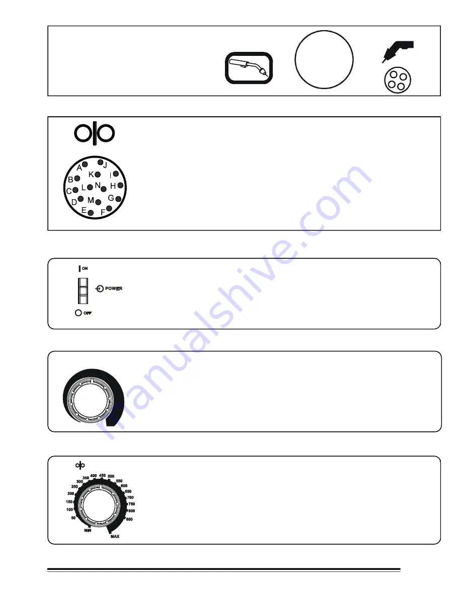
Gun Connector.
Connect gun into gun
receptacle until bottom and be sure be
perfectly tighten.
FIGURE 4-4 GUN CONNECTOR.
GUN TRIGGER
GUN
FIGURE 4-5 RECEPTACLE RC14.
RC14 RECEPTACLE.
This connector is a receptacle for a gun spool. To connect this receptacle,
align keyway, insert plug, and tighten threaded collar.
Socket Information:
SOCKET A:
24 Volts AC, 10 Amperes, 60 Hz., respect G socket (common).
SOCKET B:
Contact closure to pin A completes 24 Volts AC contactor control circuit
SOCKET G:
Circuit common for 24 and 120 VAC circuit.
SOCKET I:
120 VAC respect socket G.
SOCKET J:
Contact closure to pin I completes 120 VAC contactor control circuit.
SOCKET K:
Common
.
REMAINING SOCKETS ARE NOT USED.
INPUT POWER SWITCH.
Placing the power switch in ON
position energizes the welding power source. Placing the
power switch in the OFF position the unit shuts down.
V
SPEED
VOLTAGE

