background image

P M 13 7 9

16

1

2

3

4

5

6

7

8

9

11

12

10

13

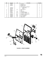
Ref.

I.D.

Quantity

1

PF0955

Front panel

1

2

PP4656

Nameplate, upper

1

3

PP4655

Nameplate, lower

1

4

Handle assembly. Consisting of:

1

MS03936

Handle support

2

MT08195

Handle 

1

5

MI01178

S2

Switch 15A 1P 1T

1

6

MP08416

Knob 

4

7

MI00110

S3

Switch 1P1T.

1

8

PT1826

PC2

PC voltmeter/ammeter

1

9

MP02512

R1, 2

Potentiometer 10KOhms, 2W

2

10

MP03020

R3, 4

Potentiometer 500KOhms, 2W

2

11

MR00503

RC1

4 sockets, receptacle

1

12

MR02583

RC2

14 pin, receptacle

1

13

MI01288

S1

Switch, power.

1

Part No.

Description

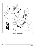
FIGURE 7-2. FRONT ASSEMBLY

Summary of Contents for MM 300-ES

Page 1: ...0 E 12 08 2021 MM 300 ES DC ARC WELDING POWER SOURCE WIRE FEEDER PROCESSES DESCRIPTION CONSTANT VOLTAGE CV MIG GMAW DC TYPEOUTPUT SINGLE PHASE 302 589 OWNER S MANUAL T M OWNER S MANUAL GIVETHISMANUALTOTHEOPERATOR ...

Page 2: ...TY PRECAUTIONS i SECTION 1 SAFETY SIGNALS AND WORDS 1 SECTION 2 SPECIFICATIONS 1 SECTION 3 INSTALLATION 3 SECTION 4 FUNCTION OF CONTROLS 7 SECTION 5 MAINTENANCE TROUBLESHOOTING 10 SECTION 6 ELECTRICAL DIAGRAM 13 SECTION 7 PARTS LIST 14 ...

Page 3: ...ged parts at once 12 Wear a safety harness to prevent falling if working above floor level 13 Keep all panels and cover securely in place ARC RAYS can burn eyes and skin NOISE can damage hearing Arc rays from the welding process produce intense heat and strong ultraviolet rays that can burn eyes and skin Noise from some processes can damage hearing 1 Wear a welding helmet fitted with a proper shad...

Page 4: ...nstalling or connecting unit 3 Have only qualified people remove guards or covers for maintenance and troubleshooting as necessary 4 To prevent accidental stating during servicing disconnect negative battery cable from battery 5 Keep hands hair loose clothing and tools away from moving parts 6 Reinstall panels or guards and close doors when servicing is finished and before starting engine SPARKS c...

Page 5: ... follow rated duty cycle Reduce current or reduce duty cycle before starting to weld again Do not block or filter airflow to unit STATIC ESD can damage PC boards Put on grounded wrist strap BEFORE handling boards or parts Use proper static proof bags and boxes to store move or ship PC boards ARC WELDING can cause interference Electromagnetic energy can interfere with sensitive electronic equipment...

Page 6: ...CATIONS Rated Weld Amperage Duty Cycle Wire Diameter Length Cooling System 250 Amperes 60 With CO2 035 to 045 0 89 to 1 14 mm 10 ft 3 m Air RECOMMENDED GUN FIGURE 2 1 VOLT AMPERE CURVES 2 1 VOLT AMPERE CURVES Thevolt amperecurvesshowthe minimum andmaximum voltage andamperageoutput capabilities of the welding source Curves of othersettingsfallbetweencurves shown A HIGHRANGE B LOW RANGE DCAMPERES DC...

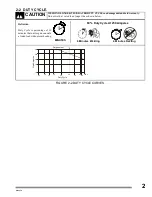
Page 7: ...IGURE 2 2 DUTY CYCLE CURVES 60 Duty Cycle At 250 Amperes MINUTES 6 Minutes Welding 4 Minutes Resting 2 2 DUTY CYCLE WELDINGLONGERTHANRATEDDUTYCYCLEcandamageunitandvoidwarranty Do not weld at rated load longer than shown below CAUTION 20 100 150 200 250 300 35 60 90 40 70 100 30 50 Duty Cycle Rated output Weld Amperes 80 ...

Page 8: ...to receptacle and tighten threated collar Check input voltage available at site 1 Jumper Links Access Door Open door 2 Jumper Link Label Check label only one is on unit 3 Input Voltage Jumper Links Movejumperlinkstomatchinput voltage Close and secure access door DCTP0022 460 VOL TS 230 VOLTS 575 VOLTS JUMPER LINKS LOCATION L1 L1 L1 L2 L2 L2 1 2 3 DCTP0022 460 V O LTS 230 V O L TS 575 V O L T S JU ...

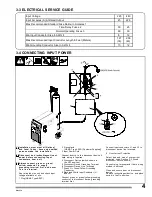
Page 9: ...ting label on unit and check input voltage available at site 1 Plug NEMA Type 6 50P 2 Receptacle NEMA Type 6 50R Customer Supplied 3 Input Power Cord Connect directly to line disconnect device if hard wiring is required 4 Disconnect Device switch shown in the OFF position 5 Disconnect Device Grounding Terminal 6 Disconnect Device Line Terminals 7 Green Or Green Yellow Grounding Conductor 8 Black a...

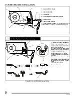
Page 10: ...PULL AND HOLD WIRE Cut off end 3 PUSHWIRE THROUGHGUIDES INTO GUN Continue holding wire 4 CLOSE AND LATCH pressure gear assembly and let go wire Install gun into receptacle and tighten locking screw 5 REMOVE CONTACT TIP and nozzle 6 PLACE SWITCH in ON position 7 PRESS TRIGGER until wire comes out of MIG gun Reinstall contact tip and nozzle on MIG gun 8 FEEDWIRETOCHECKDRIVEROLLS pressure tighten kno...

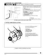
Page 11: ...t per Hour FIGURE 3 6 SHIELDED GAS CONNECTIONS 1 2 3 6 5 4 3 6 SHIELDED GAS CONNECTIONS WARNING SEE SAFETY SIGNAL AT THE BEGINING THIS MANUAL 28 5 15 8mm 1 1 8 5 8 ToolsNeeded 3 7 SPOOL WIRE INSTALLATION For 8 and 12 standard wire spools turn unit off and disconnect it 1 Hub spool 2 Pin of Hub spool 3 Wire spool Reel 4 Hud spool cap Turn the hub spool cap clockwise and remove it Install the wire s...

Page 12: ...sses With Side Shields 3 Welding Helmet Wear dry insulating gloves safety glasses with side shields and a welding helmet with a correct shade of filter see ANSI Z49 1 3 2 1 14 3mm 19mm 9 16 3 4 GUN POLARITY REVERSEPOLARITY ELECTRODEPOSITIVE STRAIGHTPOLARITY ELECTRODENEGATIVE FIGURE4 2 GUNPOLARITY GUNTRIGGER RECEPTACLE INPUT POWER SWITCH RECEPTACLE RC14 FOR SPOOL GUN GUN CONNECTOR OUTPUT WORK CABLE...

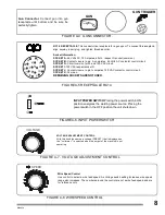
Page 13: ...ytighten FIGURE 4 4 GUN CONNECTOR GUN TRIGGER GUN FIGURE 4 5 RECEPTACLE RC14 RC14 RECEPTACLE This connector is a receptacle for a gun spool To connect this receptacle align keyway insert plug and tighten threaded collar Socket Information SOCKET A 24 Volts AC 10 Amperes 60 Hz respect G socket common SOCKET B Contact closure to pin A completes 24 Volts AC contactor control circuit SOCKET G Circuit ...

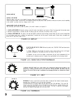
Page 14: ...pend on the position pre set in the control of the spot time 2 Burnback As soon as the torch trigger is deactivated the wire feed is suspended while the electrode wire is kept energized for a period of time established by the trimming control DIGITAL METERS DIGITAL VOLTMETER When the trigger of the gun is not activated the preset voltage value Preset is displayed When the trigger of the gun is act...

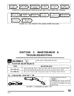
Page 15: ...nt and adjust gas at 30cfh Adjust controls and keep away GUN from work piece FIGURE5 1 CHANGINGCONTACTTIP Turn off and disconnect the unit 1 NOZZLE 2 CONTACT TIP Cut wire remaining ofthecontacttip removeNozzle remove the contact tip and install one new Reinstall nozzle ToolsNeeded 2 1 5 1 ROUTINE MAINTENANCE TIME Replace unreadable Labels Clean And Tighten Weld Terminals Tape Or Replace Cracket We...

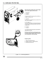
Page 16: ...utput unit stops 5 10 A fuse F1 ThefuseF1protectsthecontrolcardPC3against shortcircuitsoroverloadsproducedintheremote receptacle 14 6 Fuse F2 7 Fuse F3 ThefusesF2andF3protectsthecontrolcardPC1 against short circuits Using incorrectfusesmaydamagetheunitor the power supply network Use only original fuses same type size and rating Figure 5 2 Overload protection Replacing a fuse 1 Remove the left side...

Page 17: ... fuse F1 Check and clear any restrictions at drive assembly and liner HavenearestFactoryAuthorizedServiceStation ServiceDistributorcheckdrive motor RECOMMENDEDACTION TROUBLE Table5 2 WireDrive GunTrouble Wire feeding stops during welding Secure power cord plug in receptacle Replace building line fuse or reset circuit breaker if open Secure gun trigger plug in receptacle Power switch in On position...

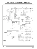
Page 18: ...A 43 S1 B Z1 GS1 VALVE RC4 F 24 Vc a RC4 B CR1 PCB 36 37 33 Vac 33 Vac 18V a c 230 a c V RC3 PLG7 RC1 PLG6 PC3 RC4 E RC4 C RC4 PLG8 MOTOR CONTROL 43 F1 10 Amp 24V a c M1 MOTOR RC4 G M RC4 H M 38 39 RC3 A RC4 A CONTACTOR RC3 E RC4 10 10V REF RC4 9 COM AND M RC3 F RC3 D RC3 C 26 27 RC5 F 24V RC5 L MIN R3 45 44 BURNBACK TIME RC5 H RC5 E RC5 D RC5 C RC5 K RC5 A SPOT RC5 J GND 49 48 S3 RC5 B MIN RC5 G ...

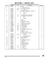
Page 19: ...00698 Capacitor 27000uF 50V 5 13 MV00768 GS1 Válve solenoid 1 14 PT2255 PC1 Pc control board 1 15 PT3636 PC3 Pc control of motor 1 16 PT3605 PC4 Pc burnback 1 17 PM0406 M1 Wire feeder mechanism fig 7 3 1 18 MT08758 CT1 Sensor Hall 1 19 PB1925 Baffle 1 20 PR0464 Bracket bottle retainer 1 21 Overload protection Consisting of MF02310 F1 Fuse 10A 1 MF02311 F2 F3 Fuse 2A 2 MP00014 Fuse holder 15A 250V ...

Page 20: ...PM1379 15 FIGURE 7 1 MAIN ASSEMBLY 9 10 2 22 4 8 26 16 15 19 12 1 28 25 3 7 29 5 17 18 23 27 21 24 11 13 6 14 20 31 32 30 ...

Page 21: ...andle support 2 MT08195 Handle 1 5 MI01178 S2 Switch 15A 1P 1T 1 6 MP08416 Knob 4 7 MI00110 S3 Switch 1P1T 1 8 PT1826 PC2 PC voltmeter ammeter 1 9 MP02512 R1 2 Potentiometer 10KOhms 2W 2 10 MP03020 R3 4 Potentiometer 500KOhms 2W 2 11 MR00503 RC1 4 sockets receptacle 1 12 MR02583 RC2 14 pin receptacle 1 13 MI01288 S1 Switch power 1 Part No Description FIGURE 7 2 FRONT ASSEMBLY ...

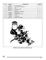
Page 22: ... 2 MB06011R Arm compl With central gear 1 3 MF02408R Shaft 1 4 MB06013R Wire pressure knob 1 5 ME02417R Drive gear 1 6 Roll Ask to your distributor 2 7 MM04283 Inlet guide tube 1 8 PP4429 Fix knob Gun loking tab 1 9 MT08685R Fix bolt 1 10 PS2098 Gun loking tab 1 11 ME02451 Moving arm central gear 1 3 11 10 8 5 6 9 4 7 ...

Page 23: ...NOTES ...

Page 24: ...NOTES ...

Page 25: ... kind will be allowed 3 Repair time should not be more than 30 days starting from the reception of the product 4 Spare parts could be adquired in the address attached to this policy 5 The customer could ask the store where he bought the product to make efective this policy IN THE FOLLOWING CASES THIS WARRANTY IS NOT VALID a The warranty will not validin the case machines have been repaired or alte...

Page 26: ...NOTES ...

Page 27: ...SERVICE CENTER FAX MAP CANADA LTD 325 Healey Road Unit 1 Bolton ON L7E 5C1 Canada Phone 905 951 2788 Toll Free 800 757 4445 Fax 905 951 6256 ...

Page 28: ......

Reviews: