


12. Position the display assembly top-side up.
13. Remove the display bezel (Section 3.25).
14. Remove the display latches and springs (Section 3.25).
15. Remove the inverter board (Section 3.21).
>>>>>>>>>>>>>>>>>>>>>>>>>>>>>>>>> CAUTION <<<<<<<<<<<<<<<<<<<<<<<<<<<<<<<<<
The ZIF connector and its attached cable can be damaged easily. Handle
only the connector slide when disconnecting the ZIF connector. Never pull
or twist the cable itself while it is seated in the ZIF connector.
>>>>>>>>>>>>>>>>>>>>>>>>>>>>>>>>>>>>><<<<<<<<<<<<<<<<<<<<<<<<<<<<<<<<<<<<<<
16. Remove the display cable and backlight cable from the inverter board
(Section 3.21).
>>>>>>>>>>>>>>>>>>>>>>>>>>>>>>>>> CAUTION <<<<<<<<<<<<<<<<<<<<<<<<<<<<<<<<<
When servicing the computer, ensure that cables are placed in their proper
location to avoid pinching during the reassembly process.
Improper cable
Summary of Contents for Series 400
Page 14: ...Chapter 1 7 System Unit Module Parts...
Page 51: ...8 Remove the battery pack Figure 3 4...
Page 69: ...8 Position the display to a 90 degree angle Figure 3 22...
Page 95: ...3 Separate the diskette drive from the bracket Figure 3 45...
Page 101: ...13 Remove the three keyboard ground clips from the system board Figure 3 51...
Page 102: ...14 Remove the left clutch ground clip from the system chassis Figure 3 52...
Page 109: ......
Page 114: ...4 Remove the bottom PC Card ejection lever from the boss on the CPU base Figure 3 64...
Page 123: ...9 Slide the trough at the rear of the CPU base to the right then lift up to remove Figure 3 73...
Page 131: ...6 Remove the display latch spring from the latch Figure 3 81...
Page 133: ...2 Slide the display latch into place on either side of the display enclosure Figure 3 83...
Page 144: ...17 Lift the display ground cable out of the display enclosure Figure 3 93...
Page 161: ...17 Lift the display ground cable out of the display enclosure Figure 3 109...
Page 186: ...6 Remove the display latch spring from the latch Figure 3 132...
Page 188: ...2 Slide the display latch into place on either side of the display enclosure Figure 3 134...
Page 204: ...17 Lift the display ground cable out of the display enclosure Figure 3 149...
Page 217: ...9 Remove the display cable from the connector on the back of the panel Figure 3 161...
Page 229: ...8 Disconnect the display ground cable 1 from the LIF clip Figure 3 172...
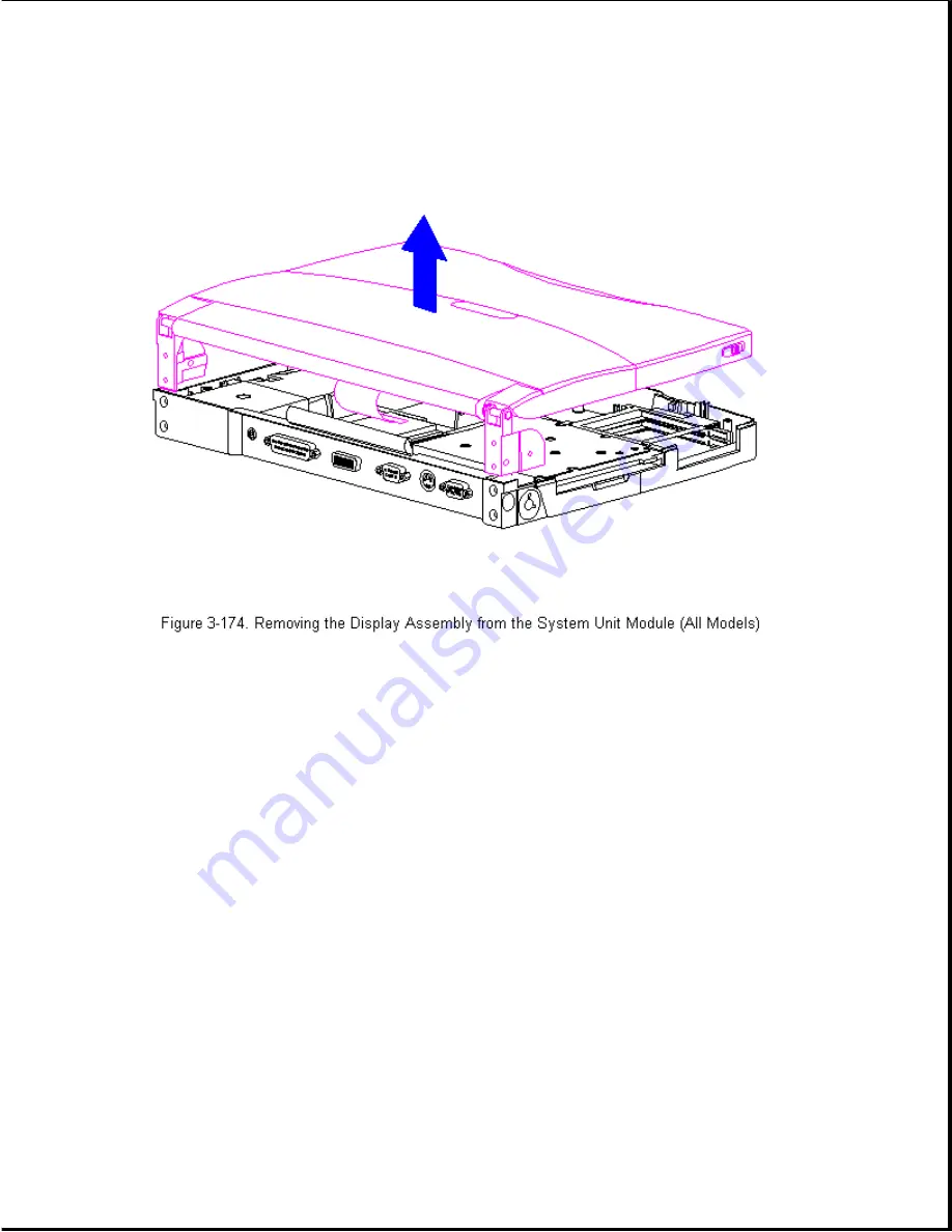
Page 231: ...11 Lift the display assembly off the system unit module Figure 3 174...
Page 236: ...28 Replace the four rear clutch screws Figure 3 179...
Page 237: ...29 Open the display to a 90 degree angle Figure 3 180...
Page 246: ...10 Lift the display assembly off the system unit module Figure 3 189...
Page 251: ...4 Remove the battery door from the docking base Figure 3 194...
Page 254: ...2 Slide the handle off the crankshaft Figure 3 197...
Page 256: ......


