


4.
Layout and Function
4.1.1 CO Option
The CMM monitors system air (air exiting the
purification system) for high levels of carbon
monoxide only while the compressor is
running.
This is controlled by two systems
comprising of a solenoid valve and auxiliary
contacts. When the motor contactor engages
it closes the auxiliary contact which sends a
signal to the CMM that the compressor is
running. Once the CMM receives this signal it
opens the supply air solenoid allowing air to
cross over the CO cell. The monitor has a built
in 5 second delay to allow the system air to
purge the ambient air in the CO cell housing
ensuring the user that the displayed reading
is accurately reading the system air free of
any ambient contamination.
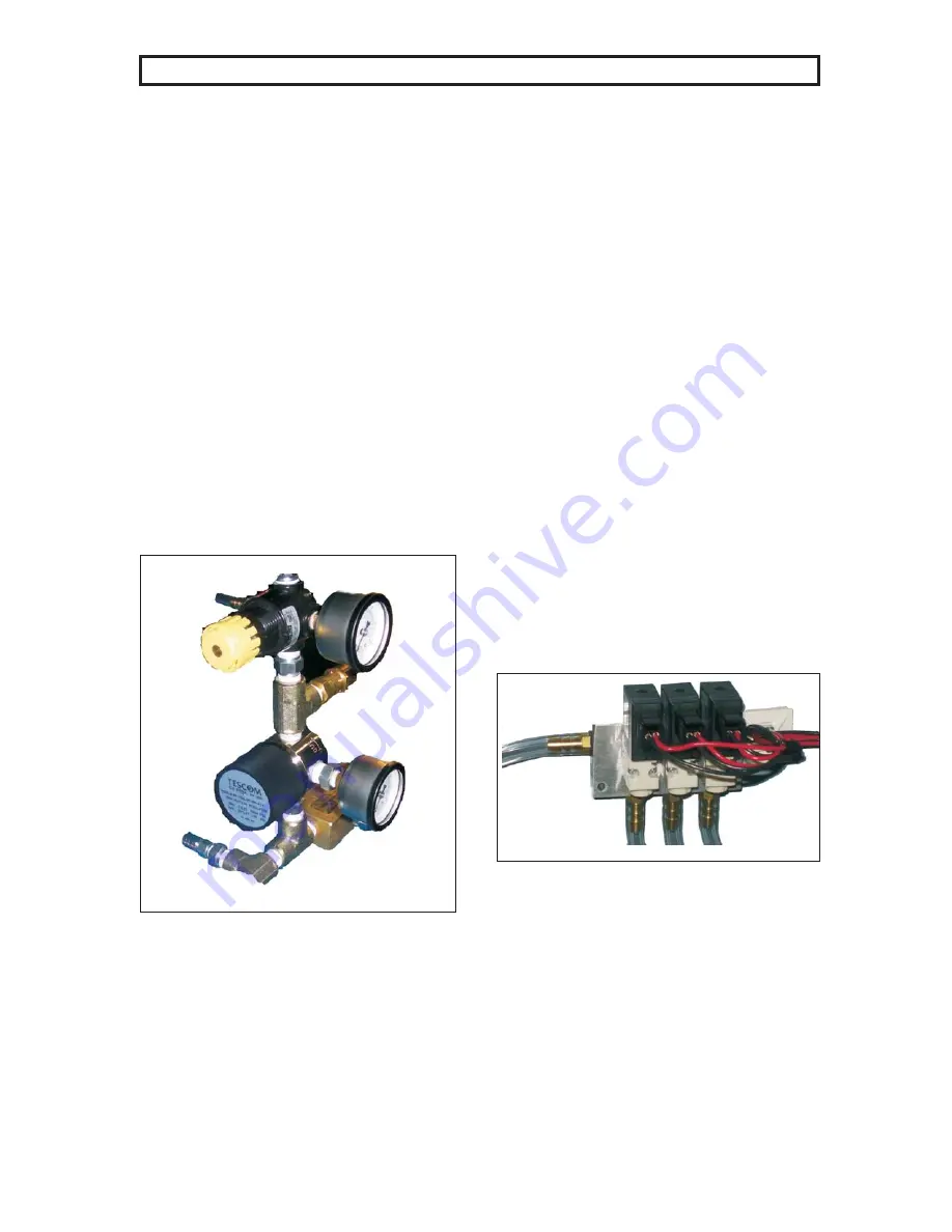
The supply air is controlled by two regulators.
These regulators reduce the system high
pressure to 5 PSI that the CMM can accurately
determine CO levels. Set the first regulator to
100 PSI and the second to 5 PSI.
fig 4.1.1-1 CO Pressure Reducing Regulators
The CMM monitors supply air input to the CO
sensor by a small pressure switch mounted on
the CMM board.
If no pressure is detected
after a short amount of time the CMM will shut
the compressor down, alarm, and indicate no
CO pressure.
This safety ensures the user
that adequate flow to the sensor is available
for proper monitoring.
Excessive heat buildup can be detrimental to
the life and operation of the CO cell. Therefore
a red rubber hose has been added to direct the
air flow out of the upper control panel and
maintain a cool environment as much as
possible.
The CMM is equipped with a
temperature
sensor
that
detects
the
temperature inside the CO sensor housing to
ensure the cell does not see temperatures
above operating levels.
Calibration can be completed in a few simple
steps. The first is to turn on the zero and
twenty
PPM
calibration
cylinders,
select
calibration from the CMM menus and then
observe monitor for completion. (See Section
6.3.3) The first step in the calibration sequence
will turn on the 20 PPM calibration solenoid and
measure the cylinder for sufficient pressure to
calibrate. If insufficient pressure is observed
an alarm will sound, stop the calibration
process, and indicate the cylinder is empty.
The second operation will be to allow flow
across the CO cell for sixty seconds. Once this
time has elapsed the twenty PPM solenoid
closes and the sequence repeats with the 0
PPM calibration cylinder.
4-2
4.1.1.1 Solenoids - CMM Control Panel
Inside the CMM control panel are three small
solenoids as shown in fig. 4.1.1.1-1.
The solenoids control the flow of the pure air
and 20ppm calibration bottles, as well as, the
inlet supply air from the compressor.
To extend the life of the CO cell the CMM limits
the flow of dry air across the cell for only the
duration of the running compressor by
operating the supply air solenoid.
fig.4.1.1.1-1 Solenoid Valves


