37
8. Servicing and maintenance
Important
The replacement of a single V-belt is not permit-
ted, always replace a complete V-belt set.
During the entire service life of the V-belt set, no
readjustment of the automatic V-belt tensioning
system will be necessary.
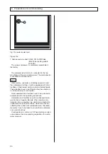
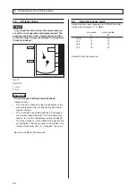
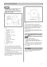
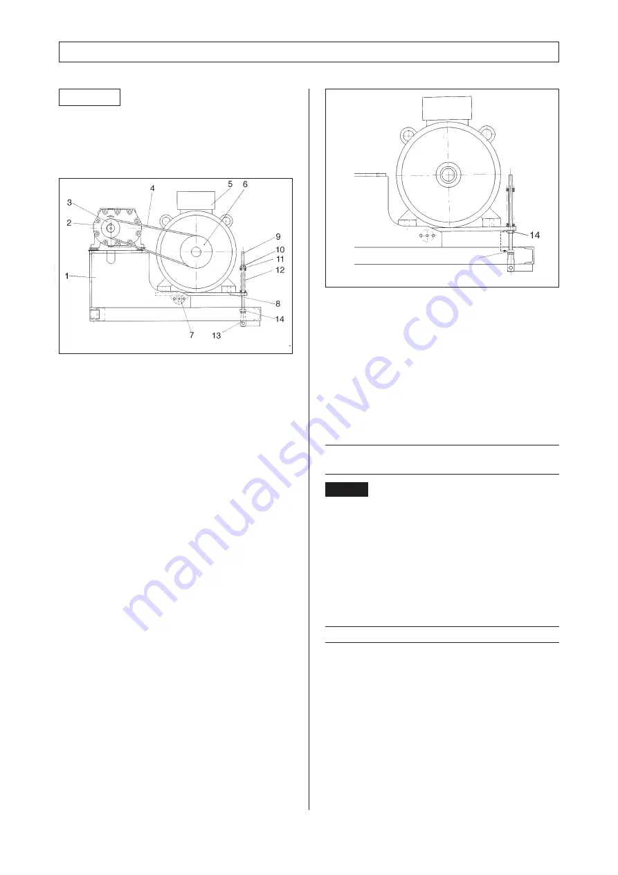
Fig. 26
1
Main frame of the drive
2
Compressor
3
V-belt pulley - compressor
4
V-belt set
5
Electric motor
6
V-belt pulley - electric motor
7
Bearing flange
8
Threaded rod
9
Distance sleeve
10
Clamping nut (self-locking)
11
Guide ring
12
Compression spring
13
Adjustment support
14
Nut
It is not permissible to loosen the bearing flange
screws (anti-vibration mount of the electric motor).
Any changes to the anti-vibration mount of the electric
motor can result in a drastic reduction in the service life
of the drive system.
The required pre-tensioning rate of the V-belt for each
screw compressor type is set in the factory.
For the adjustment after the first installation or a repla-
cement of the V-belt set, the compression spring has be
pretensioned. For this purpose, a blue marking is provi-
ded on the threaded rod.
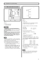
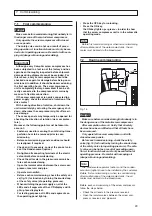
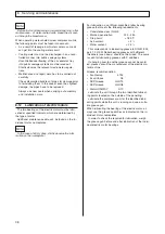
Fig. 27
8.10
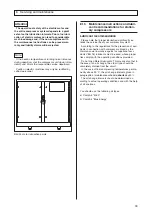
Connecting terminals in the switch
cabinet
When replacing the V-belt set, the automatic
tensioning system must be stressrelieved by means of
the nut (14) (fig. 27). After the replacement of the V-
belts, the nut (14) has to be returned to the "operation"
position (mechanical stop of the fork and clevis
combination (13)).
The compression spring has to be set to the corre-
sponding colour marking on the threaded rod using the
clamping nut (10).
Danger
.
In the case of electric voltage :
• Actuate OFF-key at the operating panel
• Set the customer-fitted main power switch to "O"
(OFF)
The connecting terminals in the switch cabinet have
to be checked and, if required, retightened during first
commissioning and later on in line with the mainte-
nance schedule.
8.11
Fittings
The fittings of the air and oil circuits have to be chek-
ked and, if required, retightened according to the
maintenance schedule.
operating position

