background image

COMPA TECH S.r.l.

Web: www.compasaw.com - E-mail: [email protected]

Tel. (+39) 059 527887 - Fax (+39) 059527889

- 31 -

ENGLISH

Operator’s handbook

6. USE

6.1 Preliminary checks

As soon as the machine is unpacked, before starting 

the motor, unlock the saw-motor arm as follows:

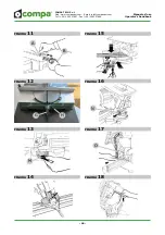
Pull knob N (fi g. 16) out and put the 

sawmotor arm to its standby position.

Make sure that the blade guard moves 

correctly and scrupulously check that the 

blade is not hindered by anything by rota-

ting it by hand.

ATTENTION:  in order not to jeopardise 

the stability of the machine during cutting 

operations, it must be secured to a stable 

structure, using the holes in the base (see 

point 5.3).

6.2  Lower part cutting operation

The cutting operation in the lower part is carried out 

as follows:

ATTENTION: Use the vices to fi rmly clamp 

the two sides of the workpiece if its shape 

and size are such as to make it diffi cult to 

safely  fi x them both on the table and 

against the rear stop. It is forbidden to 

carry out cuts on workpieces which are 

badly laid or not fi rmly fi xed. (see Fig. 41-

41A).


take the handle, press lever E (fi g.30) and slightly 

lower the saw-motor arm. Press the motor start 

button “I” (fi g.30) located on the handle and wait 

for the motor to reach operating rpm.


securely  fi x the material to be cut to the work 

base keeping it pushed with a clamp against the 

edges of the support so that it does not move 

during the cut (fi g. 15).


use the handle to lower the blade until it comes 

into contact with the material to be cut, then 

gradually push until completing the desired cut.

ATTENTION: pushing harder on the 

handle during the cut does not necessarily 

mean a faster cutting speed. On the con-

trary, it may cause excessive overloading 

of the motor and less effi cient  operation 

(the motor may breakdown and the blade 

may get damaged).


when you fi nish cutting turn off the motor by 

releasing the switch and put the saw-motor arm 

in its standby position and make sure the arm 

lock triggers.


when you fi nish cutting turn off the motor by 

pressing button “I” (fi g.30) and put the saw-

motor arm in its standby position and make sure 

the arm lock triggers.


Tips for cutting at 90° and 45° see fi g. 6B, 6C.

6.3  Cutting on the upper surface

Only for models JET when working on the 

upper surface you must mount the lower 

guard supplied with the machine. Always 

use the piece pusher during cutting opera-

tions on the upper surface.

To mount this guard proceed as follows:


if the saw-motor arm is locked in the lowered 

position, raise it (see point 5.1) and insert guard 

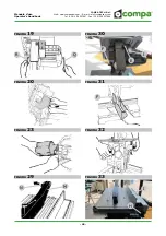
F (fi g. 31) in the support guides. Lower the saw-

motor arm and lock it centring the previously 

mounted guard.

The cutting operation on the upper surface is carried 

out as follows:


release knob N (fi g. 29) of upper guard M.


loosen knobs G (fi g. 32), set the desired cutting 

height based on the dimensions of the piece to be 

processed by raising or lowering the upper sur-

face by acting on the knob F (Fig.30). Once you 

have obtained the desired position, lock knobs G 

starting with the one closest to the operator.


loosen knobs H (fi g. 33) and adjust upper square 

I in the position required for the desired cutting 

width (indicated on the millimetre ruler printed 

on the upper surface) and lock using knobs H. 

Make sure that the upper square is parallel to the 

side of the blade.


check the operation of the upper saw guard M 

(Fig. 29) and correct locking of the upper square 

I (fi g. 33).


start the motor using the start switch “I” and put 

the piece to be cut at the beginning of the surface 

Summary of Contents for 300 JE

Page 1: ...rpi MO Italy Web www compasaw com E mail info compasaw com Tel 39 059 527887 Fax 39 059527889 Troncatrice per legno profilati in alluminio e PVC Istruzioni originali in lingua italiana 05 2015 Rev 01...

Page 2: ...o d uso rivolgeteVi al concessionario di zona Per ogni esigenza di corrispondenza scritta o tele fonica col Concessionario o con Compa Tech S r l riguardanti la macchina necessario fornire le se guent...

Page 3: ...I TECNICHE 9 3 1 Caratteristiche tecniche 9 3 2 Descrizione macchina 9 3 3 Opzionali 9 3 4 Livelli di rumorosit 10 3 5 Avvertenze specifiche di sicurezza 10 4 TRASPORTO 10 5 MESSA IN SERVIZIO 11 5 1 I...

Page 4: ...icanza ma una scelta do vuta alla delicatezza e ripercussione che quella operazione potrebbe avere sulla si curezza del prodotto ATTENZIONE Qualsiasi modalit d uso non prevista in questo manuale non d...

Page 5: ...corrispondenza della macchina potrebbe avere conseguenze molto gravi Il piano di lavoro salvo quando diversamente specificato deve trovarsi a circa 90 cm dal piano di calpestio Avere cura di scegliere...

Page 6: ...a se prevista energia pneumatica Tutte le operazioni manutentive non riportate in questo manuale devono essere eseguite da personale espressamenteautorizzato dal costrut tore ATTENZIONE E vietato per...

Page 7: ...ero in buone condizioni scollegare immediatamente il cavo e non usare la macchina ma fatela riparare presso un centro di assistenza autorizzato MANTENERE IL CAVO DI ALIMENTAZIONE IN PO SIZIONE SICURA...

Page 8: ...ibretto istruzioni della macchina Lancio di scintille e polvere verso gli occhi ed il corpo dell operatore Indossate oc chiali di protezione maschera antipolvere e abbigliamento robusto Rumore elevato...

Page 9: ...sit Tab 1 Riferimenti normativi Il collaudo acustico della macchina stato eseguito seguendo le norme UNI 7712 ISO 3740 ISO 3746 AFNOR S31069 vedi Tab 1 Condizioni di funzionamento della macchina duran...

Page 10: ...ti forniti di serie alla macchina Set chiavi per manutenzione ordinaria Manuale d uso e istruzioni Dichiarazione di conformit Asta di arresto Modello JET Spingipezzo per passate sul pianetto superiore...

Page 11: ...a detto inserire la presa d aspirazione all interno del boc chettone posteriore o al bocchettone della protezio ne superiore L utilizzo di aspirazione esterna deve comunque garantire una velocit di us...

Page 12: ...fettua nel modo seguente se il braccio bloccato in posizione abbassata sbloccarlo svitando il pomello N fig 16 ed ac compagnarlo in posizione alzata di riposo alzare leggermente l asta di collegamento...

Page 13: ...tore e un funzionamento meno efficiente pu verificarsi la rottura del motore e il danneggiamento della lama alla fine del taglio spegnere il motore premen do il pulsante I Fig 30 ed accompagnare il br...

Page 14: ...porta sega motore tenuto in posizio ne di riposo sollevato da un apposita molla In posizione di riposo a braccio alzato la lama completamente coperta dalla protezione inferiore che si scopre gradualme...

Page 15: ...empo d arresto della rotazione della lama non corrisponde ai valori stabiliti procedere alla regola zione nel seguente modo smontare il copriventola motore facendo forza con un cacciavite e tirandolo...

Page 16: ...ola Se la tavola rotante termina la propria rotazione a pi o meno di 45 effettuare la regolazione del regi stro S fig 38 posto nella parte posteriore destrae sinistra del supporto braccio 9 4 Errore n...

Page 17: ...2006 relativa alle macchine e che modifica la direttiva 98 37 CE Direttiva 2004 108 CE Compatibilit elettromagnetica Direttiva 2011 65 CE Restrizione dell uso di determinate sostanze perico lose nelle...

Page 18: ...ITALIANO Manuale d uso COMPA TECH S r l Web www compasaw com E mail info compasaw com Tel 39 059 527887 Fax 39 059527889 18 12 SCHEMI ELETTRICI SCHEMA 1 SCHEMA 3 SCHEMA 2...

Page 19: ...so 19 13 RICAMBI Indicare sempre chiaramente il modello della macchina il numero di codice dei particolari quantit dei particolari indirizzo esatto della Vs azienda Ricambi originali Il costruttore si...

Page 20: ...s reserved For any help or advice please contact your local dealer When contacting the Dealer or Compa Tech S r l in writing or by telephone please provide the following machine details Machine model...

Page 21: ...s 26 3 TECHNICAL INFORMATIONS 27 3 1 Technical features 27 3 2 Description of main parts 27 3 3 Optionals 27 3 4 Noise levels 27 3 5 Specific safety warnings 27 4 LIFTING 28 5 INSTALLATION 28 5 1 Inst...

Page 22: ...t a choice due to the consequences that the operation could have on product safety ATTENTION Any use not covered in this manual should not be performed by the user It is not an oversight but a choice...

Page 23: ...ry serious consequences The work surface unless specified otherwise should be about 90 cm from the floor Make sure that you choose an area with adequa te lighting ATTENTION Place the machine on a flat...

Page 24: ...It is forbidden for the user to perform any maintenance work not co vered in this manual The manufacturer considers these operations complex and may compromise the integrity of the ma chine and as a...

Page 25: ...its position at all times DO NOT USE THE MACHINE IN PRESENCE OF LIQUIDS Do not wet the machine with liquids or expose it to damp environments Do not leave it outdoors USE AN EXTENSION CABLE THAT IS SU...

Page 26: ...inju re hands Wear protective gloves and keep a safe distance from the grinding area Lethal electric shock hazard Do not touch live parts and keep safe distance Before every maintenance operation dis...

Page 27: ...Economic manual clamp Vertical clamp Laser 3 4 Noise level Tab 1 Reference standards The noise level test on the machine was carried out according to the following standards UNI 7712 AFNOR S31069 Tab...

Page 28: ...e Use and instruction manual Declaration of conformity Stop rod Mod JET Piece pusher for upper surface work Lower guard Upper support square Make sure that all the standard and optio nal accessories a...

Page 29: ...t 28 m s 5 6 Adjustments 5 6 1 Positioning the stop rods This device is used as a reference stop for cutting va rious pieces of the same length and can be mounted either on the right or on the left si...

Page 30: ...sed standby position pull in and at the same time pull up lever O fig 17 in order to rotate inner guard P fig 18 insi de the sawmotor arm to its limit lock the motor shaft by inserting a 6mm Allen spa...

Page 31: ...peed On the con trary it may cause excessive overloading of the motor and less efficient operation the motor may breakdown and the blade may get damaged when you finish cutting turn off the motor by r...

Page 32: ...to unlock it see point 5 1 The saw motor arm is kept raised in standby position with a spring In standby position with arm raised the blade is completely covered by the lower guard and is gradually u...

Page 33: ...ime If the blade rotation stop time does not correspond to the established values adjust it as described below remove the motor fan cover using a screwdriver and pulling it towards the outside push th...

Page 34: ...the correct position 9 3 Incorrect maximum table rotation If the rotating table stops its rotation at more or less 45 adjust regulator S fig 38 located on the right and left rear part of the support a...

Page 35: ...ng Direc tive 98 37 EC Directive 2004 108 EC Electromagnetic compatibility Directive 2011 65 EC Restriction of use of certain hazardous substances in electrical and electronic equipment Italian Legisl...

Page 36: ...COMPA TECH S r l Web www compasaw com E mail info compasaw com Tel 39 059 527887 Fax 39 059527889 36 ENGLISH Operator s handbook 12 ELECTRIC DIAGRAMS WIRING 1 WIRING 3 WIRING 2...

Page 37: ...27889 37 ENGLISH Operator s handbook 13 SPARE PARTS Always indicate clearly the machine model the part code the part quantity the exact address of your company Original spare parts The manufacturer di...

Page 38: ...COMPA TECH S r l Web www compasaw com E mail info compasaw com Tel 39 059 527887 Fax 39 059527889 38 Manuale d uso Operator s handbook GREZZO QUALITY Esploso JE...

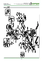
Page 39: ...COMPA TECH S r l Web www compasaw com E mail info compasaw com Tel 39 059 527887 Fax 39 059527889 39 Manuale d uso Operator s handbook 1 101 814 61 8 6 8 6 56 44 56 37 6 8 814 61 Esploso JET...

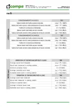
Page 40: ...COMPA TECH S r l Web www compasaw com E mail info compasaw com Tel 39 059 527887 Fax 39 059527889 40 Manuale d uso Operator s handbook TAB 1...

Page 41: ...COMPA TECH S r l Web www compasaw com E mail info compasaw com Tel 39 059 527887 Fax 39 059527889 41 Manuale d uso Operator s handbook FIGURA 1 6 8 7 9 1 4 10 2 3 5 11 13 12...

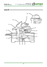
Page 42: ...COMPA TECH S r l Web www compasaw com E mail info compasaw com Tel 39 059 527887 Fax 39 059527889 42 Manuale d uso Operator s handbook FIGURA 2 1 3 4 5 2...

Page 43: ...CH S r l Web www compasaw com E mail info compasaw com Tel 39 059 527887 Fax 39 059527889 43 Manuale d uso Operator s handbook FIGURA 8 FIGURA 9 FIGURA 10 D C F E FIGURA 3 FIGURA 5 FIGURA 7 FIGURA 4 F...

Page 44: ...l Web www compasaw com E mail info compasaw com Tel 39 059 527887 Fax 39 059527889 44 Manuale d uso Operator s handbook FIGURA 11 FIGURA 12 FIGURA 13 FIGURA 14 FIGURA 15 FIGURA 16 FIGURA 17 FIGURA 18...

Page 45: ...Web www compasaw com E mail info compasaw com Tel 39 059 527887 Fax 39 059527889 45 Manuale d uso Operator s handbook FIGURA 19 FIGURA 20 FIGURA 23 R Q FIGURA 29 N M FIGURA 31 FIGURA 30 FIGURA 32 FIGU...

Page 46: ...MPA TECH S r l Web www compasaw com E mail info compasaw com Tel 39 059 527887 Fax 39 059527889 46 Manuale d uso Operator s handbook FIGURA 34 FIGURA 35 FIGURA 36 FIGURA 37 FIGURA 38 I L P R 90 45 45...

Page 47: ...COMPA TECH S r l Web www compasaw com E mail info compasaw com Tel 39 059 527887 Fax 39 059527889 47 Manuale d uso Operator s handbook FIGURA 39 FIGURA 40 FIGURA 41 FIGURA 41A 90 45 T...

Page 48: ...COMPA TECH S r l Web www compasaw com E mail info compasaw com Tel 39 059 527887 Fax 39 059527889 48 Manuale d uso Operator s handbook FIGURA 43...

Page 49: ...COMPA TECH S r l Web www compasaw com E mail info compasaw com Tel 39 059 527887 Fax 39 059527889 49 Manuale d uso Operator s handbook NOTE...

Page 50: ...COMPA TECH S r l Web www compasaw com E mail info compasaw com Tel 39 059 527887 Fax 39 059527889 50 Manuale d uso Operator s handbook NOTE...

Page 51: ...COMPA TECH S r l Web www compasaw com E mail info compasaw com Tel 39 059 527887 Fax 39 059527889 51 Manuale d uso Operator s handbook NOTE...

Page 52: ...m E mail info compasaw com Tel 39 059 527887 Fax 39 059527889 52 Manuale d uso Operator s handbook COMPA TECH S r l Via Piemonte 11 15 41012 Carpi MO Italy Tel 39 059 527887 Fax 39 059527889 Web www c...

Reviews: