


COMPA TECH S.r.l.
Web: www.compasaw.com - E-mail: [email protected]
Tel. (+39) 059 527887 - Fax (+39) 059527889
- 29 -
ENGLISH
Operator’s handbook
in the rear part of the base in order to keep it from
overturning.
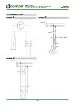
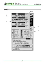
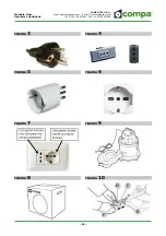
5.4 Electrical connection
Before connecting the machine to the electrical net-
work (see point 2.7 and Fig. 7), ensure that the vol-
tage of the motor indicated on the label on the motor
corresponds to the voltage of the power supply line.
WARNING! Ensure that the earth wire is
connected to the building’s earth system.
the motor (type S3 - 50%) is designed for inter-
mittent periodic use, it should not be left on for a
long time for no reason.
if it is necessary to use extension cords, make
sure that the cord size is suitable for withstan-
ding the intensity of the current absorbed by
the machine. It is advisable to use the shortest
extension cords possible.
always remove the plug from the socket before
effecting any type of maintenance work or blade
replacement on the machine.
do not ever leave the machine with the plug
connected to the mains.
do not move or handle the machine with the plug
connected to the mains.
Your cropper is provided with double insulation.
In other words, it has two independent insulation
barriers to prevent contact between metallic parts,
offering further protection against the hazard of
electrocution.
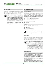
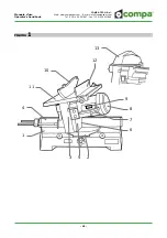
5.5 Suction connection
The machine is set-up for being connected to a sha-
vings collection bag (optional) via a rear opening or
a separate suction device (fi g. 9).
To connect the machine to the abovementioned suc-
tion device, place the suction intake inside the rear
opening or at the upper guard opening. Use of an
external suction must guarantee an output speed of
suctioned air of at least 28 m/s.
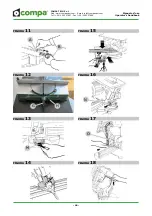
5.6 Adjustments
5.6.1 Positioning the stop rods
This device is used as a reference stop for cutting va-
rious pieces of the same length and can be mounted
either on the right or on the left side of the machine.
The various adjustments that can be assigned to
stop E (fi g. 10) are made by loosening knobs A (fi g.
11) and D and moving rods B and F and clamp C in
the direction indicated by the arrows.
Remember to tighten the previously loosened
ATTENTION! Make sure that the stop rod
is never in the trajectory of the blade de-
scent.
5.6.2 Table angle adjustment
The rotating table can be moved to the right or left
in 4 fi xed positions: 15°- 22°30’-30°- 45° and in the
central position at 0°.
To unlock the table to rotate it to the above angles,
loosen (if tightened) knob G (fi g. 12). Turn knob H
clockwise as far as possible and rotate the saw motor
arm using the specifi c handle.
When the desired angle indicated on the specifi c
ruler (printed on the rotating table) lines up with the
fi xed index on the base, stop and return knob to the
starting position by rotating it anticlockwise as far
as it will go thus locking the rotating table in to the
position you reached. Then further lock with knob H
to prevent vibrations while cutting.
Before starting rotation make sure that
there is nothing that prevents it (e.g. sha-
vings, pieces from previous processing
etc.). Before cutting make sure that the
saw motor arm is locked by moving it to-
wards the left and right.
Locking in intermediate angles is obtained
by unlocking the rotating table as described
above and once the desired position is
obtained locking it with knob G.
5.6.3 Arm angle adjustment
The saw-motor arm can be only inclined to the left
up to a maximum of 45° (end position) and with the
rotating table in position 0o (see point 5.6.2).
Mod. JET
For greater freedom of movement in incli-
ned cuts, fi rst raise the upper surface to its
maximum height (see point 6.3).