ATC200-LITE-USB Teletilt
®
RET System
Section 13–Device Configuration with SmartBeam™ Antennas
Bulletin 639536 • Revision L
October
2014
13-3
4. SmartBeam antennas do not change the assigned
Antenna Model
.
For the most current listing of antenna models designed for use with the ATC200-LITE-USB
Teletilt system, see the Products tab on the CommScope website.
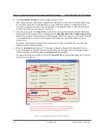
5. Use
the
Antenna Type
drop down list to select the antenna type that is correct for the antenna
model selected (Figure 13-2). Note that this value is used for reference only and has no direct
affect upon the Actuator/Antenna that is being configured.
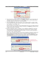
6. The serial number of SmartBeam antennas is pre-set and cannot be changed.(Figure 13-2).
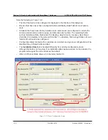
7. Using the drop down lists and entry fields, specify the parameters for the remaining fields (Op-
erating/Frequency Band, Technology, Base Station ID, Installer ID, Install Date, Mechanical Tilt,
Bearing, Height, Sector, and Location). Note the following:
• A positive mechanical tilt angle means that the antenna beam is directed below the
horizontal plane. A negative mechanical tilt angle means that the antenna beam is
directed above the horizontal plane.
• The bearing is the installed compass orientation for this antenna.
• The height of the antenna on the tower must be entered in the range of 1 to 999. No
specific unit of length, such as feet or meters, is associated with this field. However,
you should enter a value that conforms to the units of length customarily used by your
company for antenna installations.
• If in AISG 1.1 mode, the ID for the base station associated with this antenna must be 1 to
12 characters in length, and it may contain any combination of numbers and letters.
When the actuator is in AISG 2.0 protocol mode, the longer station ID consists of 32
characters.
• The Installation Date field is handled differently from all other configuration items. Although
this field is not required, if no installation date has been saved on the actuator the program
will suggest the current date as the default. If the current date is used, it will be saved on
the actuator when the
Configure
button is activated. Alternately, the suggested date may
be erased and a new date entered, or the field may be left blank. When a date is entered,
it must be formatted as MM/DD/YY as shown in Figure 13-2 (A
forward slash
character
placed between the month and day and a
forward slash
character placed between the day
and year) i.e., July 7, 2008 would be typed as 07/07/08.
• The installer’s ID must be 1 to 5 characters in length with any combination of letters
and
numbers.
• Values specified for the frequency band, sector, technology, location, and mechanical tilt are
used for reference only and have no direct affect upon the actuator/antenna that is being
configured.
•
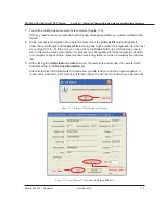
Frequency band (AISG 1.1)/Operating Band (AISG 2.0) value can have multiple values set.
Click on the drop down arrow in the list to open the multi selection list. Make selection by click-
ing on the check box for the relevant frequency. Click outside the list or press ESC key to close
the list (Figure 13-3).
Summary of Contents for Teletilt ATC200-LITE-USB
Page 2: ......
Page 11: ...Bulletin 639536 Revision L October 2014 Part 1 Initial Setup ...
Page 27: ...Bulletin 639536 Revision L October 2014 Part 2 Uploading Firmware ...
Page 36: ...October 2014 Bulletin 639536 Revision L Part 3 Device Discovery for All Types of Antennas ...
Page 113: ...Bulletin 639536 Revision L October 2014 Part 7 Saving Reports and Retrieving Alarm Status ...
Page 143: ...Bulletin 639536 Revision L October 2014 Part 9 Appendix ...
Page 145: ...Bulletin 639536 Revision L October 2014 A 1 Appendix A Letter of Compliance ...
Page 147: ...Bulletin 639536 Revision L October 2014 B 1 Appendix B Declaration of Conformity ...


