CommScope ICX7400-1X40GQ Hardware Installation Manual Download Page 47

Ruckus ICX 7450 Switch Hardware Installation Guide

45

Part Number: 53-1003899-09


Power supplies

The Ruckus ICX 7450 supports alternating-current (AC) and direct-current (DC) power supplies. The Ruckus ICX 7450 is capable of 
running on one power supply and one fan. The second power supply and second fan provide redundancy.

If the second power supply and second fan slot are unused, you must cover them with filler panels.

NOTE

Ruckus recommends that the Ruckus ICX 7450 switch operates with two power supplies and two fan trays installed. If a power 
supply or fan tray fails, it must be replaced as soon as possible.

NOTE

AC and DC power supplies cannot be installed and used in the same device. Mismatched power supplies in the same device 
cause continual reboot on power up.

Power supply usage

The Ruckus ICX 7450-24P, ICX 7450-32ZP, and ICX 7450-48P models support specific AC or DC power supply inputs and numbers 
of POE, POE+, High PoE, and PoH ports.

Using a second power supply

In the event of an AC power loss or power supply failure, a redundant power supply (second power supply) can be installed as a backup 
power source to a switch. Each power supply provides a load-sharing and redundant power source (up to 250 W AC or 510 W DC for 
non-PoE switches, and 1000 W AC or 510 W DC for PoE switches). 

Ruckus recommends that you pay attention to the PoE, PoE+, High PoE, and PoH port configuration (referred to as PoE in this section) of 
the switch when using a redundant power supply. When using a single power supply, a PoE switch has a maximum number of supported 
PoE ports. Ruckus recommends that when a redundant power source is used for a PoE switch, that the maximum number of PoE ports 
supported by the switch must not exceed that which can be supported by a single power supply. 
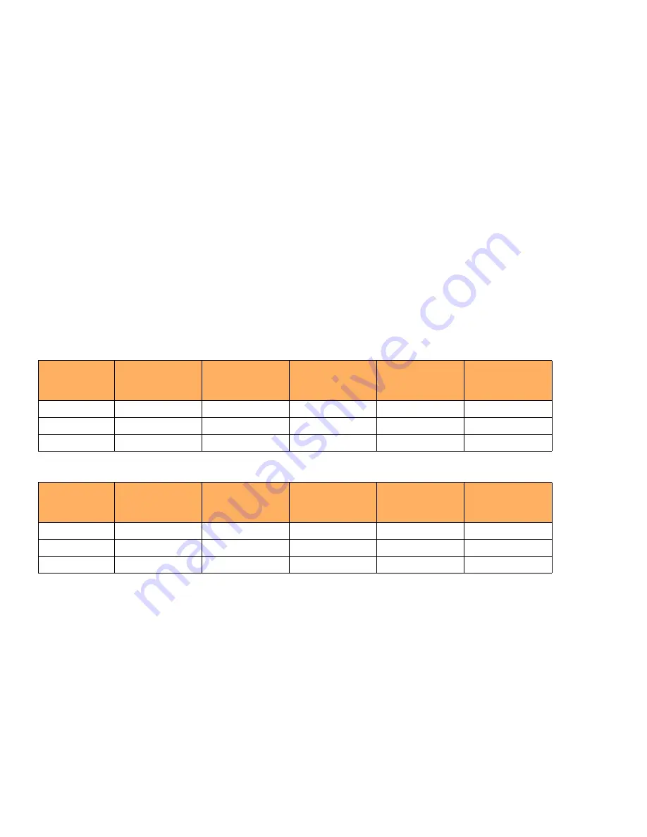
TABLE 8

AC power supply and PoE usage

Model

Maximum PoE 
output power draw 
(Watts)

Maximum number 
of PoE ports 
supported (15.4W)

Maximum number 
of PoE+ ports 
supported (30W)

Maximum number 
of High PoE ports 
supported (60W)

Maximum number 
of PoH ports 
supported (95W)

ICX 7450-24P

748 Watts

24

24

8

7

ICX 7450-32ZP

748 Watts

32

24

8

7

ICX 7450-48P

748 Watts

48

24

8

7

TABLE 9

DC power supply and PoE usage

Model

Maximum p ower 
draw from DC line 
input (Watts)

Maximum number 
of PoE ports 
supported (15.4W)

Maximum number 
of PoE+ ports 
supported (30W)

Maximum number 
of High PoE ports 
supported (60W)

Maximum number 
of PoH ports 
supported (95W)

ICX 7450-24P

258.5 Watts

16

8

4

2

ICX 7450-32ZP

258.5 Watts

16

8

4

2

ICX 7450-48P

258.5 Watts

16

8

4

2

Summary of Contents for ICX7400-1X40GQ

Page 1: ...Part Number 53 1003899 09 Publication Date 8 October 2020 RUCKUS ICX 7450 Switch Hardware Installation Guide HARDWARE INSTALLATION GUIDE ...

Page 2: ...OM COMPUTER VIRUS AND WARRANTIES ARISING FROM COURSE OF DEALING OR COURSE OF PERFORMANCE CommScope does not represent or warrant that the functions described or contained in the Materials will be uninterrupted or error free that defects will be corrected or are free of viruses or other harmful components CommScope does not make any warranties or representations regarding the use of the Materials i...

Page 3: ...le switches 11 Views of the Ruckus ICX 7450 switch 12 Ruckus ICX 7450 slot and Ethernet port numbering 15 Supported expansion modules 17 Supported transceivers and cables 19 QSFP 40GBase SR BD support 19 Installing the Ruckus ICX 7450 Shipping carton contents 21 Installation and safety considerations 22 Electrical considerations 22 Environmental considerations 22 Location considerations 22 Rack co...

Page 4: ...stalling a DC power supply 47 Attaching a PC or terminal 48 Connecting to the management port 49 Installing an SFP or SFP transceiver 49 Connecting network devices 50 Connectors 50 Connecting a network device to a copper port 50 Connecting a network device to a fiber port 51 Ruckus ICX 7450 Operation LED activity interpretation 53 Ruckus ICX 7450 front panel LEDs 53 Ruckus ICX 7450 rear panel LEDs...

Page 5: ...fications per PSU 78 Power consumption typical configuration 78 Power consumption maximum configuration 79 Power consumption modules 80 Data port specifications Ethernet 81 Serial port specifications pinout mini USB 81 Serial port specifications pinout RJ 45 82 Serial port specifications protocol 82 Memory specifications 82 Regulatory compliance EMC 82 Regulatory compliance safety 83 Regulatory co...

Page 6: ...4 Ruckus ICX 7450 Switch Hardware Installation Guide Part Number 53 1003899 09 ...

Page 7: ...old and italic text identify command syntax components Delimiters and operators define groupings of parameters and their logical relationships TABLE 1 Text conventions Convention Description Example monospace Identifies command syntax examples device config interface ethernet 1 1 6 bold User interface UI components such as screen or page names keyboard keys software buttons and field names On the ...

Page 8: ... Other technical documentation content is available without logging into the Ruckus Support Portal White papers data sheets and other product documentation are available at https www ruckuswireless com Convention Description Boldface text Identifies command names keywords and command options Italics text Identifies a variable value In Fibre Channel products a fixed value provided as input to a com...

Page 9: ...e section Priority 2 P2 High Network or service is impacted but not down Business impact may be high Workaround may be available Go to the Open a Case section Priority 3 P3 Medium Network or service is moderately impacted but most business remains functional Go to the Self Service Resources section Priority 4 P4 Low Request for information product documentation or product enhancements Go to the Se...

Page 10: ...vices and Support Using these resources will help you to resolve some issues and will provide TAC with additional data from your troubleshooting analysis if you still require assistance through a support case or RMA If you still require help open and manage your case at https support ruckuswireless com case_management ...

Page 11: ...is document 9 What s new in this document The following table includes descriptions of new information added to this edition TABLE 2 Summary of enhancements added to this edition Feature Description Described in Power and cooling Added information on fan speeds and temperature thresholds Monitoring power and cooling ...

Page 12: ...10 Ruckus ICX 7450 Switch Hardware Installation Guide Part Number 53 1003899 09 About this Document What s new in this document ...

Page 13: ... four 1 10 GbE SFP ports 10 GbE copper module with four 1 10 GbE RJ 45 ports Two 40 GbE QSFP or four 10 GbE SFP stacking ports supporting stacking for up to twelve switches Dual redundant hot swappable fan trays available with intake or exhaust airflow One Gigabit Ethernet port RJ 45 and one serial management port mini USB to configure and manage the switch through the CLI One USB port for the tra...

Page 14: ...r supply side exhaust airflow fan two fans required with two power supplies ICX FAN10 I Ruckus ICX 7450 power supply side intake airflow fan two fans required with two power supplies CC MINIUSB RJ45 Console cable male mini USB to male RJ 45 ICX7450 RMK FRU Rack mount kit 2 post ICX 7450 XBR R000295 FRU Universal rack mount kit 4 post 24 32 inch depth rack DX6740T VDX6740T 1G PCEURO Power Cord for ...

Page 15: ...h PoE PoH is limited to ports 1 8 FIGURE 3 Front view of the Ruckus ICX 7450 32ZP 1 System LEDs 6 Mini USB console port 2 Media Stacking module LEDs 7 Reset button 3 Stack unit ID display 8 10 100 1000Base T RJ 45 ports 1 1 1 1 1 24 4 Management port RJ 45 9 SFP SFP 1 2 1 1 2 4 QSFP 1 2 1 5 USB port for flash drive 1 System LEDs 6 Mini USB console port 2 Media Stacking module LEDs 7 Reset button 3...

Page 16: ...o ports 1 48 High PoE PoH is limited to ports 1 8 FIGURE 5 Front view of the Ruckus ICX 7450 48P 1 System LEDs 6 Mini USB console port 2 Media Stacking module LEDs 7 Reset button 3 Stack unit ID display 8 10 100 1000Base T RJ 45 ports 1 1 1 1 1 48 4 Management port RJ 45 9 SFP ports 1 2 1 1 2 4 5 USB port for flash drive 1 System LEDs 6 Mini USB console port 2 Media Stacking module LEDs 7 Reset bu...

Page 17: ... require users to enter port numbers as part of the command syntax and many show command outputs display port numbers The port numbers are entered and displayed in stack unit slot number port number format 1 System LEDs 6 Mini USB console port 2 Media Stacking module LEDs 7 Reset button 3 Stack unit ID display 8 SFP port LEDs 1 1 1 1 1 48 4 Management port RJ 45 9 SFP ports 1 2 1 1 2 4 5 USB port ...

Page 18: ... 1 24 and 2 5 GbE RJ 45 ports 1 1 25 through 1 1 32 with odd port numbers on the top row and port 1 1 1 on the left Slot 2 contains 1 10 GbE SFP ports 1 2 1 and 1 2 3 on the top row left to right and ports 1 2 2 and 1 2 4 on the bottom row left to right Refer to the following figure FIGURE 9 Ruckus ICX 7450 32ZP slot numbering Slot 1 and Slot 2 are located on the front of the Ruckus ICX 7450 48 an...

Page 19: ...and ports 1 4 2 and 1 4 4 on the bottom row left to right Refer to Figure 12 FIGURE 12 Ruckus ICX 7450 rear slot numbering Supported expansion modules A 4 port 1 GbE SFP expansion module can be installed in the slots shown in Table 4 on page 18 and Table 6 on page 18 The expansion module supports 1 GbE optics refer to the Ruckus Optics Family Data Sheet A 4 port 1 10 GbE SFP expansion module can b...

Page 20: ...es Yes Yes Yes Yes Yes ICX7400 1X40GQ 40G 4X10G 40G 4X10G 40G 4X10G Yes No Yes No Yes No TABLE 5 Ruckus ICX 7450 32ZP expansion slots and supported media modules Module Slot 2 Slot 3 Slot 4 ICX7400 4X10GF 4X10G 4X1G 4X10G 4X1G 4X10G 4X1G Yes Yes Yes Yes Yes Yes ICX7400 4X10GC 4X10G 4X1G 4X10G 4X1G 4X10G 4X1G Yes Yes Yes Yes Yes Yes ICX7400 1X40GQ 40G 4X10G 40G 4X10G 40G 4X10G No No Yes No Yes No T...

Page 21: ... support The Ruckus ICX 7450 supports 40GBASE SR BD bi directional BiDi QSFP transceivers with duplex LC optics The 40 GbE BiDi optics support two 20 GbE channels over duplex fiber cable with the transmit and receive of each channel operating at two wavelengths on a single fiber The 40 GbE BiDi transceivers enable 40 GbE links to be supported on installed 10 GbE duplex fiber infrastructure This tr...

Page 22: ...20 Ruckus ICX 7450 Switch Hardware Installation Guide Part Number 53 1003899 09 Ruckus ICX 7450 Overview Supported transceivers and cables ...

Page 23: ...ms included in the shipping carton When unpacking the device verify that the contents of the shipping carton is complete if any items are missing contact the place of purchase The Ruckus ICX 7450 device An accessory kit containing the following items Rack mounting kit containing two L shaped mounting brackets and two sets of eight sink head screws Two post rack kit containing four rack mounting sc...

Page 24: ...itch ensure that the following environmental requirements are met Because the Ruckus ICX 7450 can be ordered with fans that move air either front to back or back to front be sure to orient your switch with the airflow pattern of any other devices in the rack All equipment in the rack should force air in the same direction to avoid intake of exhaust air Some combinations of intake and exhaust airfl...

Page 25: ...way The rack is secured to ensure stability in case of unexpected movement such as an earthquake Recommendations for cable management Cables can be organized and managed in a variety of ways for example use cable channels on the sides of the rack or patch panels to reduce the potential for tangling the cables The following list provides some recommendations for cable management NOTE You should not...

Page 26: ...quirements outlined in this manual Powering on the system on page 44 6 Attach a terminal or PC to the device This will enable you to configure the device through the command line interface CLI Attaching a PC or terminal on page 48 7 Assign a password for additional access security No default password is assigned to the CLI Ruckus FastIron Management Configuration Guide 8 Before attaching equipment...

Page 27: ...atings of all devices installed on the same circuit as the device Compare this total with the rating limit for the circuit The maximum ampere ratings are usually printed on the devices near the input power connectors CAUTION Disconnect the power cord from all power sources to completely remove power from the device CAUTION Before plugging a cable to any port be sure to discharge any static charge ...

Page 28: ...vice in a rack NOTE You need a 2 Phillips screwdriver for installation Before mounting the switch in a rack pay particular attention to the following factors Temperature Because the temperature within a rack assembly may be higher than the ambient room temperature check that the rack environment temperature is within the specified operating temperature range Refer to Environmental considerations o...

Page 29: ... Figure 15 FIGURE 15 Two post rack mounting positions NOTE Use the following procedure when installing the Ruckus ICX 7450 in a two post rack For four post racks follow the procedure in Installing the 1U 1 5U and 2U Universal Kit for Four Post Racks XBR R000295 on page 29 Use the following steps to mount the Ruckus ICX 7450 in a two post rack 1 Remove the rack mount kit from the shipping carton Th...

Page 30: ...nder the switch until the rail kit is secured to the rack 4 Attach the front right bracket to the rail rack using two 10 32 x 5 8 in screws and the appropriate round hole or square hole retainer nuts 5 Repeat step 4 to attach the left front bracket to the left front rack rail and tighten all 10 32 x 5 8 in screws to a torque of 25 in lb 29 cm kg Refer to Figure 17 FIGURE 17 Installing the Ruckus I...

Page 31: ...ation and facility requirements for your product before mounting the device Refer to the hardware installation guide for your product for more information Use Electronic Industries Association EIA standard racks Provide space in a 19 in 48 3 cm EIA rack as required for the device type with a minimum distance of 24 in 609 60 mm and a maximum distance of 32 in 812 80 mm between the front and back po...

Page 32: ...owing tasks to install the device in a four post rack 1 Attaching the front brackets on page 31 2 Attaching the extension brackets to the device on page 31 3 Installing the device in the rack on page 32 4 Attaching the rear brackets to the extensions on page 33 5 Attaching the rear brackets to the rack posts on page 34 1 Front brackets 2 6 Screw 8 32 x 5 16 in panhead Phillips 8 2 Bracket extensio...

Page 33: ...9 Attaching the front brackets Attaching the extension brackets to the device Complete the following steps to attach the extension brackets to the device There are medium and long extension brackets that you can use for this step Choose the correct extension bracket for the depth of your rack 1 Select the proper length extension bracket for your rack depth 2 Position the right extension bracket al...

Page 34: ... shown in Figure 21 providing temporary support under the device until the rail kit is secured to the rack 2 Attach the right front bracket to the right front rack post using two 10 32 x 5 8 in panhead screws and two retainer nuts Use the upper and lower holes in the bracket 3 Attach the left front bracket to the left front rack post using two 10 32 x 5 8 in panhead screws and two retainer nuts Us...

Page 35: ... bracket for your rack depth 2 Slide the right rear bracket onto the right extension as shown in Figure 22 The short rear brackets are shown Use the first and third vertical pairs of holes for the screws Refer to Figure 23 for the positioning of the medium or long brackets and screws 3 Attach the brackets using four 6 32 x 1 4 in panhead screws 4 Repeat step 2 and step 3 to attach the left rear br...

Page 36: ...ttach the rear brackets to the rack posts 1 Attach the right rear bracket to the right rear rack post using two 10 32 x 5 8 in panhead screws and two retainer nuts as shown in Figure 24 Use the upper and lower holes in the bracket 2 Attach the left rear bracket to the left rear rack post using two 10 32 x 5 8 in panhead screws and two retainer nuts Use the upper and lower holes in the bracket 3 Ti...

Page 37: ...ations in the rack installation procedures are for reference only and may not show the actual device Complete the following tasks to install the device in a four post rack 1 Attaching the front brackets to the rear of the device on page 36 2 Attaching the extensions to the front of the device on page 36 3 Installing the device in the rack on page 37 4 Attaching the rear brackets to the extensions ...

Page 38: ...bracket and then into the holes on the side of the device Use the upper and lower screw holes leaving the center holes empty 3 Repeat Step 1 and Step 2 to attach the left rear bracket to the left side of the device 4 Tighten all the 8 32 x 5 16 in screws to a torque of 15 in lb 17 cm kg FIGURE 25 Attaching the front brackets to the rear of the device Attaching the extensions to the front of the de...

Page 39: ...ition the device in the rack as shown in Figure 27 providing temporary support under the device until the rail kit is secured to the rack 2 Attach the right front bracket to the right rear rack post using two 10 32 x 5 8 in panhead screws and two retainer nuts Use the upper and lower holes in the bracket 3 Attach the left front bracket to the left rear rack post using two 10 32 x 5 8 in panhead sc...

Page 40: ...rect bracket for the depth of your rack 1 Select the proper length rear bracket for your rack depth 2 Slide the right rear bracket onto the right extension as shown in Figure 28 The short rear brackets are shown Use the first and third vertical pairs of holes for the screws Refer to Figure 29 for the positioning of the medium or long brackets and screws 3 Attach the brackets using four 6 32 x 1 4 ...

Page 41: ...attach the rear brackets to the front rack posts 1 Attach the right rear bracket to the right front rack post using two 10 32 x 5 8 in screws and two retainer nuts as shown in Figure 30 Use the upper and lower holes in the bracket 2 Attach the left rear bracket to the left front rack post using two 10 32 x 5 8 in screws and two retainer nuts Use the upper and lower holes in the bracket 1 Rear brac...

Page 42: ...s a group of devices Ruckus stackable units and their connected stacking links that are connected so that the stack is managed as a single entity You can mix any Ruckus ICX 7450 models together in a stack A stack cannot contain other device types Stacking ports There are two QSFP ports on the rear panel that can be used as stacking ports The following figure shows these ports in slot 3 and slot 4 ...

Page 43: ...Gbps stacking on the rear panel and 4x10 Gbps stacking on the front panel cannot be configured at the same time Stacking configuration requirements Before configuring the stack using the CLI physically connect the devices using stacking cables For information about configuring a stack refer to the Ruckus FastIron Stacking Configuration Guide Stacking cables Use QSFP direct attached copper stacking...

Page 44: ...cal first and last devices forming a ring or closed loop The closed loop connection provides a redundant path for the stack link so if one link fails stack communications can be maintained For example in a three unit stack using a ring topology unit 1 connects to unit 2 unit 2 connects to unit 3 and unit 3 connects to unit 1 Figure 34 shows a supported rear panel ring stacking topology FIGURE 34 R...

Page 45: ...53 1003899 09 FIGURE 35 Front panel linear stacking topology Figure 36 shows a supported front panel ring stacking topology FIGURE 36 Front panel ring stacking topology NOTE For more information about stacking refer to the Ruckus FastIron Stacking Configuration Guide ...

Page 46: ...tion to the grounding point on the rack no paint or isolating surface treatment 3 Crimp the included grounding lug to a grounding wire of at least 12 American Wire Gauge AWG The 12 AWG wire and grounding lug should be crimped together using a proper tool 4 Attach the 12 AWG stranded copper wire to the grounding terminal on the Ruckus ICX 7450 using the screw included in the grounding kit 5 Attach ...

Page 47: ... provides a load sharing and redundant power source up to 250 W AC or 510 W DC for non PoE switches and 1000 W AC or 510 W DC for PoE switches Ruckus recommends that you pay attention to the PoE PoE High PoE and PoH port configuration referred to as PoE in this section of the switch when using a redundant power supply When using a single power supply a PoE switch has a maximum number of supported ...

Page 48: ...device The airflow direction of the power supply must match that of the installed fan trays All must be either exhaust or intake Installing an AC power supply Use the following steps to install an AC power supply in the Ruckus ICX 7450 FIGURE 38 Installing an AC power supply unit 1 If replacing a power supply remove the previously installed power supply from the appropriate slot by removing the tw...

Page 49: ...talling a DC power supply NOTE AC and DC power supplies cannot be installed and used in the same device Mismatched power supplies in the same device cause continual reboot on power up Use the following steps to install a DC power supply in the Ruckus ICX 7450 1 Remove the previously installed power supply from the appropriate slot by removing the chassis attachment screws located in the upper righ...

Page 50: ...he connector 9 When you are sure the power supply has properly engaged the connector tighten the chassis attachment screws to secure the power supply in the slot When the Ruckus ICX 7450 is powered on the power LED on the front of the device should turn green to confirm that the power supply is correctly installed and supplying power Refer to Ruckus ICX 7450 front panel LEDs on page 53 Attaching a...

Page 51: ...r To prevent unauthorized access Ruckus recommends that the management port only be connected to a secure private network To manage the Ruckus ICX 7450 through its management port connect the port to the management Ethernet network using Category 5 or better cable Management of the Ruckus ICX 7450 is described in detail in the Ruckus FastIron Management Configuration Guide Installing an SFP or SFP...

Page 52: ...ect position to insert an SFP or SFP transceiver in the lower row of ports is with the gold plated edge up FIGURE 41 Installing an SFP or SFP transceiver in a port slot Connecting network devices Ruckus devices support connections to other vendors routers switches and hubs as well other Ruckus devices Connectors For port pinouts refer to Serial port specifications pinout mini USB on page 81 Connec...

Page 53: ...ceiver Ruckus strongly recommends cleaning the cable connectors and the port connectors For more information refer to Cleaning the fiber optic connectors on page 51 3 Gently insert the cable connector a tab on each connector should face upward into the transceiver connector until the tabs lock into place 4 Observe the link and activity LEDs to determine if the network connections are functioning p...

Page 54: ...52 Ruckus ICX 7450 Switch Hardware Installation Guide Part Number 53 1003899 09 Installing the Ruckus ICX 7450 Connecting network devices ...

Page 55: ...tivity Two power supply unit PSU bicolor status LEDs green and amber labeled PSU1 and PSU2 One DIAG diagnostic bicolor status LED green and amber One MS stacking configuration bicolor status LED green and amber Three MOD media expansion module monocolor status LEDs green Ten stack ID stack identifier monocolor indicator LEDs green 24 1 GbE port status LEDs green for 1 GbE and amber for 10 100 Mbps...

Page 56: ...Four 1 GbE SFP port bicolor status LEDs green for 1 GbE and amber for 10 100 Mbps Ethernet which indicate 1 GbE or 10 100 Mbps Ethernet mode of operation 10G SFP module LEDs Four 1 10 GbE SFP port bicolor status LEDs green for 10 GbE and amber for 1 GbE which indicate 1 GbE or 10 GbE mode of operation 40G QSFP module LEDs Four 40 GbE QSFP port bicolor status LEDs green for 1x40 GbE and amber for 4...

Page 57: ...ports 1 24 green for 1 GbE and amber for 10 100 Mbps Ethernet which indicate 1 GbE or 10 100 Mbps Ethernet mode of operation 8 2 5 GbE port bicolor status LEDs for ports 25 32 green for 2 5 GbE and amber for 100 1000 Mbps Ethernet which indicate 2 5 GbE 1 GbE or 100 Mbps Ethernet mode of operation 32 PoE port monocolor status LEDs green for providing power to attached device 1 Management port spee...

Page 58: ...Ds green and amber labeled PSU1 and PSU2 One DIAG diagnostic bicolor status LED green and amber One MS stacking configuration bicolor status LED green and amber Three MOD media expansion module monocolor status LEDs green Ten stack ID stack identifier monocolor indicator LEDs green 48 1 GbE bicolor port status LEDs green for 1 GbE and amber for 10 100 Mbps Ethernet which indicate 1 GbE or 10 100 M...

Page 59: ... The Ruckus ICX 7450 48P has the following LEDs on the front panel Two management port status LEDs green for speed and link activity Two power supply unit PSU bicolor status LEDs green and amber labeled PSU1 and PSU2 One DIAG diagnostic bicolor status LED green and amber One MS stacking configuration bicolor status LED green and amber Three MOD media expansion module monocolor status LEDs green 1 ...

Page 60: ... the LEDs on the Ruckus ICX 7450 48P front panel The up arrow port status LEDs for the 1 GbE ports correspond to the upper odd numbered ports the down arrow port status LEDs correspond to the lower even numbered ports FIGURE 46 Ruckus ICX 7450 48P front panel LEDs NOTE PoE PoE power is available to ports 1 48 High PoE PoH is limited to ports 1 8 1 Management port speed and link activity LEDs 6 Por...

Page 61: ...dicate 1 GbE or 10 GbE mode of operation 40G QSFP module LEDs One 40 GbE QSFP port bicolor status LED green for 1x40 GbE and amber for 4x10 GbE which indicates 1x40 GbE mode of operation Figure 47 shows the LEDs on the Ruckus ICX 7450 48F front panel The up arrow port status LEDs for the 10 GbE ports correspond to the upper odd numbered ports the down arrow port status LEDs correspond to the lower...

Page 62: ...of the Ruckus ICX 7450 FIGURE 48 Ruckus ICX 7450 rear panel LEDs LED patterns The following tables describe the Ruckus ICX 7450 LED patterns 1 FAN2 fan tray LED 5 MOD3 power LED 2 MOD4 40 GbE QSFP link activity LED for stacking 6 FAN1 fan tray LED 3 MOD4 power LED 7 PSU2 status LED 4 MOD3 40 GbE QSFP link activity LED for stacking 8 PSU1 status LED TABLE 10 Management port left 10 100 1000 Mbps st...

Page 63: ... or the switch is operating in standalone mode No action required Blinking green Device is initializing No action required Steady green Stacking mode is enabled and the switch is the stack master No action required Steady amber Stacking mode is enabled and the switch is the standby controller No action required Blinking amber Stacking mode is initializing and the switch is in stacking master arbit...

Page 64: ...ets are being transmitted or received No action required TABLE 19 RJ 45 PoE LEDs LED state Status of hardware Recommended action Steady green Port is providing PoE1 power to a connected device 1 Indicates PoE PoE High PoE or PoH No action required Off Port is not providing PoE power No action required TABLE 20 100 1000 Mbps SFP module port LEDs LED state Status of hardware Recommended action Off n...

Page 65: ...de QSFP module port LEDs left side LED LED state Status of hardware Recommended action Off no light Not cabled No action required Steady green Link is up in 40 GbE mode MOD2 data uplink mode or MOD3 MOD4 stacking mode No action required Blinking green There is 40 GbE traffic and packets are being transmitted or received No action required TABLE 24 4x10 GbE mode QSFP module port LEDs LED state Stat...

Page 66: ...2 F The shutdown level is the temperature at which the device reboots It is set by the device and is not configurable When the device temperature reaches the shutdown level it generates a warning message that the device s temperature is over the shutdown level and the device shuts down in two minutes The system restarts 120 seconds after the device reaches the temperature shutdown level The switch...

Page 67: ...el Number 23 0000144 03 Serial Number CZG2L23R04H Firmware Ver 32 65 Power supply 2 Fan Air Flow Direction Front to Back Fan 1 not present Fan 2 ok speed auto 1 2 Fan controlled temperature 37 1 deg C Fan speed switching temperature thresholds Speed 1 NM 66 deg C Speed 2 56 85 deg C shutdown Fan 2 Air Flow Direction Front to Back Slot 1 Current Temperature 30 6 deg C Sensor 1 37 3 deg C Sensor 2 3...

Page 68: ...66 Ruckus ICX 7450 Switch Hardware Installation Guide Part Number 53 1003899 09 Ruckus ICX 7450 Operation Monitoring power and cooling ...

Page 69: ... ICX 7450 is powered on and running This section provides information about the following tasks Removing a copper or fiber optic transceiver Cabling a fiber optic transceiver Cleaning the fiber optic connectors Removing a fiber optic transceiver While removing a fiber optic transceiver be sure to wear an ESD wrist strap that is connected to ground To remove a fiber optic transceiver from an SFP SF...

Page 70: ...ace 3 Observe the link and active LEDs to determine if the network connections are functioning properly Cleaning the fiber optic connectors To avoid problems with the connection between the fiber optic transceiver SFP SFP or QSFP and the fiber cable connectors Ruckus strongly recommends cleaning both connectors each time you disconnect and reconnect them Dust can accumulate in the connectors and c...

Page 71: ... pulls air in from the rear side of the switch and exhausts it out the front side This is called back to front airflow or reverse airflow The show chassis command displays a device s airflow direction Front to Back or Back to Front Replacing a power supply unit NOTE Maintain all power supply and fan trays in operational condition to provide redundancy CAUTION Remove the power cord from a power sup...

Page 72: ...Before opening the package that contains the power supply touch the bag to the switch casing to discharge any potential static electricity Ruckus recommends using an ESD wrist strap during installation 3 Remove the power supply from the anti static shielded bag 4 Ensure that the replacement power supply has the same part number and airflow label as the power supply being replaced 5 Unplug the powe...

Page 73: ...ly must have the same part number and the same airflow label as the fan assembly being replaced refer to Figure 49 on page 69 for the location of the airflow label A 1 Phillips screwdriver Installing or replacing the fan assembly Complete the following steps to install or replace a fan assembly in a Ruckus ICX 7450 1 If replacing a fan assembly a Using a Phillips screwdriver unscrew the captive sc...

Page 74: ...ICX 7450 includes one front panel slot and two rear panel slots for media expansion or service modules including a 4 port SFP 1 GbE module a 4 port SFP 10 GbE module a 4 port Copper 10 GbE module or a 1 port QSFP 40 GbE module The slots in which these modules can be installed are listed in Table 4 on page 18 If not installed the empty expansion module slot must be covered using the filler panel Ti...

Page 75: ...any potential static electricity It is recommended that you wear an ESD wrist strap during installation 5 Remove the expansion module from the anti static shielded bag 6 Holding the expansion module level guide it into the carrier rails on each side and gently push it all the way into the slot ensuring that it firmly engages with the connector 7 When you are sure the expansion module has properly ...

Page 76: ...74 Ruckus ICX 7450 Switch Hardware Installation Guide Part Number 53 1003899 09 Managing the Ruckus ICX 7450 Replacing an expansion module or service module ...

Page 77: ...PoE switches Shipping bundle has one power supply and one fan unit Fans One dual redundant hot swappable fan unit with intake or exhaust airflow Cooling Forced air cooling front to back or back to front System architecture Non blocking shared memory switch ICX 7450 24 24 1 GbE RJ 45 ports four 10 GbE SFP uplink ports two 40 GbE QSFP stacking ports one power supply and one fan unit ICX 7450 24P 24 ...

Page 78: ...45 front panel ports 24 1 GbE RJ 45 ports for ICX 7450 24 24P 32ZP 48 1 GbE RJ 45 ports for ICX 7450 48 48P 24 48 slot 1 2 5 GbE RJ 45 front panel ports 8 2 5 GbE RJ 45 ports for ICX 7450 32ZP 8 slot 1 1 GbE SFP front panel ports 48 1 GbE SFP for ICX 7450 48F 48 slot 1 Ethernet management port 1 RJ 45 port with 10 100 1000 Mbps auto negotiating capability N A System component Description Switch st...

Page 79: ...48F 4 37 cm 1 72 inches 40 00 cm 17 32 inches 39 37 cm 15 50 inches 6 80 kg 14 99 lb 8 94 kg 19 71 lb Condition Operational Non operational Ambient Temperature 5 C to 50 C 23 F to 122 F NOTE Maximum operation temperature of 50 C applies to sea level and decreases by 1 C for every 1000 feet altitude increase per NEBS rule If Back to Front airflow is chosen and only a single fan is in service maximu...

Page 80: ...0 24 399 973 Hours ICX 7450 24P 317 719 Hours ICX 7450 32ZP 568 376 Hours ICX 7450 48 376 635 Hours ICX 7450 48P 297 862 Hours ICX 7450 48F 330 154 Hours N A Power supply model Maximum output power rating DC Input voltage Input line frequency Maximum input current Input line protection Maximum inrush current AC RPS15 E 250 W 100 240V 50 60Hz 4 0A Fuses 35A AC RPS15 I 250 W 100 240V 50 60Hz 4 0A Fu...

Page 81: ...367 BTU hr 1 x 250 W AC 1 x 510 W DC 1 PSU 129 4 W 451 BTU hr 128 4 W 438 BTU hr 115 94 W 396 BTU hr 1 x 250 W AC 1 x 510 W DC 2 PSUs ICX 7450 48P 129 7 W 443 BTU hr 143 W 488 BTU hr 115 1W 393 BTU hr 1 x 1000 W AC 1 x 510 W DC 1 PSU no PoE load 128 2 W 438 BTU hr 141 1 W 482 BTU hr 118 82W 406 BTU hr 1 x 1000 W AC 1 x 510 W DC 2 PSUs no PoE load ICX 7450 48F 141 4 W 420 BTU hr 139 6 W 477 BTU hr ...

Page 82: ... 1000 W AC 1 x 510 W DC 2 PSUs required for PoE loading ICX 7450 48F 178 3 W 609 BTU hr 175 7 W 606 BTU hr 167 1W 570 BTU hr 1 x 250 W AC 1 x 510 W DC 1 PSU 196 4 W 670 BTU hr 194 1 W 663 BTU hr 177 64W 606 BTU hr 1 x 250 W AC 1 x 510 W DC 2 PSUs Name Description Power consumption ICX7400 4X1GF 4 port 1 GbE SFP expansion module Typical 5 40 W Maximum 5 76 W ICX7400 4X10GF 4 port 1 10 GbE SFP expan...

Page 83: ...s with PoE support ICX 7450 48 40 GbE 2 ICX7400 1X40GQ QSFP stacking ports compatible with LR4 or SR4 optical transceivers or direct attached copper cable 10 GbE 4 ICX7400 4X10GC SFP uplink ports compatible with ER LR LRM SR ZR or USR optical transceivers 1 GbE 4 ICX7400 4X1GF SFP uplink ports compatible with SX or LX optical transceivers 1 GbE 48 slot 1 RJ 45 ports ICX 7450 48P 40 GbE 2 ICX7400 1...

Page 84: ...E mark Immunity for Information Technology Equipment ICES 003 Canada Class A 4 Reserved Not used 5 GND Ground Pin Signal Description 1 Not supported N A 2 Not supported N A 3 UART1_TXD Transmit data to ICX 4 GND Logic ground 5 Not supported N A 6 UART1_RXD Receive data from ICX 7 Not supported N A 8 Not supported N A Parameter Value Baud 9600 Data bits 8 Parity None Stop bits 1 Flow control None M...

Page 85: ...ardous substance in electrical and electronic equipment EU RoHS 2012 19 EU Waste electrical and electronic equipment EU WEEE 94 62 EC packaging and packaging waste EU 2006 66 EC batteries and accumulators and waste batteries and accumulators EU battery directive 1907 2006 of the European Parliament and of the Council of 18 December 2006 concerning the Registration Evaluation Authorisation and Rest...

Page 86: ...84 Ruckus ICX 7450 Switch Hardware Installation Guide Part Number 53 1003899 09 Ruckus ICX 7450 Specifications Regulatory compliance environmental ...

Page 87: ...y cause harmful interference to radio communications Operation of this equipment in a residential area is likely to cause harmful interference in which case the user will be required to correct the interference at his own expense Industry Canada statement Cet appareil numérique de la classe A est conforme à la norme NMB 003 du Canada English translation of above statement This Class A digital appa...

Page 88: ...t based on the standard of the Voluntary Control Council For Interference by Information Technology Equipment VCCI If this equipment is used in a domestic environment radio disturbance may arise When such trouble occurs the user may be required to take corrective actions Korea English translation of above statement Class A device Broadcasting Communication Device for Office Use This device obtaine...

Page 89: ...ion Guide 87 Part Number 53 1003899 09 China English translation of above statement This is a Class A product In a domestic environment this product may cause radio interference in which case the user may be required to take adequate measures ...

Page 90: ...kus ICX 7450 Regulatory Statements BSMI statement Taiwan BSMI statement Taiwan English translation of above statement Warning This is a class A product In a domestic environment this product may cause radio interference in which case the user may be required to take adequate measures ...

Page 91: ...0 24P E ICX7450 24P 40G E ICX7450 24P E2 㙕䠢 ŊńřĸĵĶıĮĵĹġ 偈㙕䠢 ICX7450 48 E ICX7450 48P ICX7450 48P E ICX7450 48P E2 ICX7450 48P E RMT3 ICX7450 48P STK E ICX7450 48P STK E RMT3 㙕䠢 ŊńřĸĵĶıĮĵĹŇġ 偈㙕䠢 ICX7450 48F E ICX7450 48F E RMT3 ICX7450 48F E2 Declaration of the Presence Condition of the Restricted Substances Marking Equipment name Type designation Type Restricted substances and its chemical symbols...

Page 92: ...90 Ruckus ICX 7450 Switch Hardware Installation Guide Part Number 53 1003899 09 Ruckus ICX 7450 Regulatory Statements BSMI statement Taiwan ...

Page 93: ...églementé uniquement Une zone à accès réglementé est un local qui n est accessible que par le personnel d entretien à l aide d un outil verrou ou clé conçus à cet effet ou de tout autre accessoire de sécurité et qui est contrôlé par l autorité responsable de ce local PRECAUCIÓN Todos aquellos dispositivos con fuentes de alimentación de CC Ruckus ICX 7450 están diseñados para su instalación en zona...

Page 94: ...f près des connecteurs d entrée d alimentation PRECAUCIÓN Verifique que el instrumento no sobrecargue los circuitos de corriente el cableado y la protección para sobrecargas Para determinar la posibilidad de sobrecarga en los circuitos de suministros añada las capacidades nominales de corriente amp de todos los instrumentos instalados en el mismo circuito que el instrumento Compare esta suma con e...

Page 95: ... instrumento puede estar encendido mientras se instala o retira un suministro de corriente pero el suministro de corriente en sí no deberá conectado a la corriente CAUTION Risk of explosion if battery is replaced by an incorrect type Dispose of used batteries according to the manufacturer s instructions VORSICHT Es besteht Explosionsgefahr wenn ein unzulässiger Batterietyp eingesetzt wird Verbrauc...

Page 96: ...apa correspondiente puesta en la ranura Si pone en funcionamiento el dispositivo con una ranura descubierta el sistema se sobrecalentará CAUTION For the DC input circuit to the system of a Ruckus ICX 7450 make sure there is a 20 Amp circuit breaker minimum 60 VDC double pole on the input lugs to the power supply The input wiring for connection to the product should be Listed copper wire 12 AWG mar...

Page 97: ...ho de cable de EEUU El cable de tierra debe estar acoplado al conector de entrada de CC según se muestra en la Figure 40 el otro extremo se conecta al suelo del edificio CAUTION Power supplies are hot swappable However they should be inserted or removed without a power cord being connected to a power source to avoid damage VORSICHT Netzteile sind hot swap fähig Sie sollten jedoch eingesetzt oder e...

Page 98: ...es sources d alimentation pour couper complètement l alimentation du dispositif PELIGRO Para desconectar completamente la corriente del instrumento desconecte el cordón de corriente de todas las fuentes de corriente DANGER If the installation requires a different power cord than the one supplied with the device make sure you use a power cord displaying the mark of the safety agency that defines th...

Page 99: ...aser Products GEFAHR Laserstrahlung Schauen Sie nicht direkt mit optischen Instrumenten in den Laserstrahl herein Klasse 1M Laserprodukte DANGER Rayonnement de laser Ne regardez pas directement avec les instruments optiques Produits de laser de la classe 1M PELIGRO Radiacion de Laser No vea directamente con Instrumentos Opticos Clase 1M de Productos de Laser ...

Page 100: ...98 Ruckus ICX 7450 Switch Hardware Installation Guide Part Number 53 1003899 09 Ruckus ICX 7450 Cautions and Danger Notices Danger notices ...

Page 101: ... 2020 ARRIS Enterprises LLC All rights reserved Ruckus Wireless Inc a wholly owned subsidiary of ARRIS International plc 350 West Java Dr Sunnyvale CA 94089 USA www ruckuswireless com ...

Reviews: